

How To Create A Home Appliance App For Embedded And Android
Made by TotalCross / Displays / Home Automation / Sensors / IoT
About the project
Building house automatization with the Home Appliance application and interact with Android devices using Firebase platform in order to store the data. You will also learn how to use external Python scripts on the Java application, GPIO interfacing, and building a graphical user interface using TotalCross.
Project info
Difficulty: Easy
Platforms: Android, Raspberry Pi, Python, Java, Arm
Estimated time: 1 hour
License: MIT license (MIT)
Items used in this project
Hardware components


Software apps and online services
Story
Building home automation with Java for Linux Arm and mobile devices
In this article, you will learn how to automate your house with the Home Appliance application and how to interact with your Android device using some great technologies, including the Firebase platform in order to store the data. You will also learn how to use external Python scripts on the Java application, GPIO interfacing, and how to build a graphical user interface using TotalCross.
Introduction:
First of all, let's talk about the running application. The image below shows the running application on Raspberry Pi 4 with a small 5-inch display.
Picture 1 - Embedded application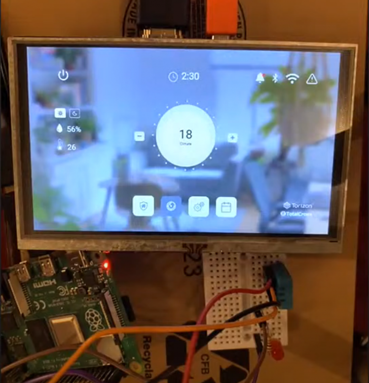
The embedded application is based on reading the commands list from the Firebase service, and running them on Raspberry Pi. This method allows communication between the embedded and the mobile application.
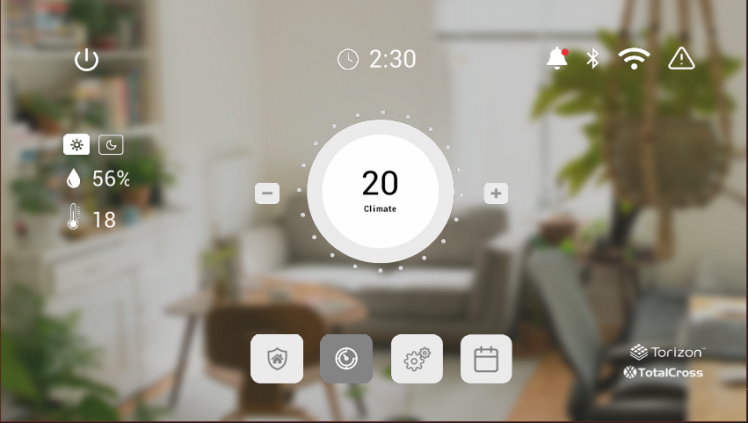
The mobile application is a little simpler, without the sensor readings, it has a simple UI which is used only to change the temperature, with two buttons for power. The mobile app’s job is to send commands to the Firebase server which will be executed by the embedded application.
Picture 2 - Mobile application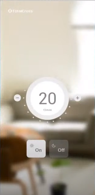
To build the application you need to install the following tools:
For the physical test you will need the following additional hardware:
Source code
Clone the source code from https://github.com/TotalCross/embedded-samples/tree/main/home-appliance and open the project.
After opening the project on VScode, make a first run of the application to generate runtime files. To do so, right click on the HomeApplianceXMLApplication.java file and then click on RUN. After the first run, just close the application, and now we can go to the configuration.
Configuring the home appliance application
In this project, we have two main configuration files: the FirebaseConfig.java and the UIconfig.java. The first one we use to configure the Firebase service and the second one we use to select the UI of the project.
UIconfig.java
On the UI configuration, we can select between two interfaces, the LIGHT_XML_LAYOUT, for use on embedded devices with restricted resources, and the BEAUTIFUL_XML_LAYOUT. We can change the selected interface by changing the variable LAYOUT_TO_INITIALIZE.
- public abstract class UIConfig {
- private UIConfig() {
- }
- /**
- * Lightweight layout to low RAM devices
- */
- public static final String LIGHT_XML_LAYOUT =
- "xml/homeApplianceLightXML.xml";
- /**
- * Beautiful layout for more advanced devices
- */
- public static final String BEAUTIFUL_XML_LAYOUT=
- "xml/homeApplianceBeautifulXML.xml";
- /**
- * App XML layout that will be loaded by MainWindow
- */
- public static final String LAYOUT_TO_INITIALIZE = BEAUTIFUL_XML_LAYOUT;
- }
In the following, you can see the two possible GUIs:
Picture 3 - The lighter interface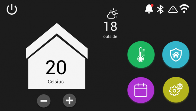
Picture 4 - The beautiful interface
FirebaseConfig.java
Using the Firebase configuration file, we're going to change the parameters for your Firebase application.
Change "YOUR AUTH KEY" to the authorization key given by Firebase, and change the "YOUR FIREBASE URL" to the URL of your firebase application
- public abstract class FirebaseConfig {
- private FirebaseConfig() {
- }
- /**
- * Firebase Realtime Database Secret Key.
- */
- private static final String FIREBASE_AUTH_KEY = "YOUR AUTH KEY";
- /**
- * Firebase Realtime Database Commands document base URL.
- */
- public static final String COMMANDS_FIREBASE_URL = "YOUR FIREBASE URL"
- + FIREBASE_AUTH_KEY;
- }
Working on the application
Now with the UI and Firebase configured, the application is ready to be deployed and run in the embedded device, but first we're going to talk a little bit about working on the application and its interaction with the environment.
UI from XML
To make it easiest to create the interface we are using the Knowcode-Xml XmlContainerLayout. This feature allows us to use a pre-mounted interface with its XML; in this case, we are using the chosen XML on the UI configuration file.
- final XmlContainerLayout xmlCont = (XmlContainerLayout) XmlContainerFactory
- .create(UIConfig.LAYOUT_TO_INITIALIZE);
- // Swapping from MainWindow to XmlContainerLayout.
- swap(xmlCont);
Event mapping
For the user to interact with the application, we need to add events to itself. To do this, we’ll instance the object reference on Java using the Knowcode-XML, for example, the minus button
- // Getting Button instance that matches with "android:id" tag in xml.
- // This button will decrease temp inside selector
- final Button minusButton=(Button) xmlCont.getControlByID("@+id/minus");
After instantiating the object, you can make any changes to it. For example, we add the press listener to the minus button.
- minusButton.addPressListener(new PressListener() {
- @Override
- public void controlPressed(ControlEvent e) {
- if (insideTempLabel != null) {
- // Sets label text decreasing temp
- insideTempLabel.setText(Convert.toString(--insideTemp));
- }
- }
- });
Firebase communication
The Firebase communication is implemented on the listening function, which is responsible for making HTTP requests to the real-time database, with the credentials settings that we configured on the previous topic. The HTTP response from the database should contain the commands sent by the mobile application; the embedded one gets the list of commands and does the necessary actions to accomplish them.
- URI uri = new URI(FirebaseConfig.COMMANDS_FIREBASE_URL.concat("&orderBy="timestamp""));
- // Performing query
- String response = HTTPConnection.doGet(uri);
- if (response == null || response.equalsIgnoreCase("null"))
- return; // returning to prevent NullPointerException
- /*
- * Parsing response in JSON Objects to get commands from remote.
- */
- JSONObject data = new JSONObject(response);
- List<JSONObject> listCommands = new ArrayList<JSONObject>();
- JSONArray ids = data.names();
- JSONArray array = data.toJSONArray(ids);
- for (int i = 0; i < array.length(); i++) {
- JSONObject command = array.getJSONObject(i);
- String id = ids.getString(i);
- command.put("id", id);
- listCommands.add(command);
- }
GPIO usage
The LED control is made by using the “gpiod” feature from the TotalCross framework. This feature interacts with the GPIO kernel device driver, allowing the application to control the GPIO chip.
- import totalcross.io.device.gpiod.GpiodChip;
- import totalcross.io.device.gpiod.GpiodLine;
- if (Settings.platform.equalsIgnoreCase("linux_arm")) {
- // Opening Gpio chip
- gpioChip = GpiodChip.open(0);
- // Gets Gpio line
- pin = gpioChip.line(21);
- // Request line as output and set the initial state to low
- pin.requestOutput("CONSUMER", 0);
- }
Temperature and humidity reading
To read the temperature of the environment, we’ll use the DHT11 sensor, which is capable of reading the temperature and humidity data and sending it through the one wire protocol to the embedded device.
In the application, this communication is implemented by a Python script which uses the Adafruit_DHT library to read data from the sensor. On Java we instance the Python script on a Linux process and read its outputs, returning the reading of the Python process to the main application.
- public String readTemp() {
- // Returns default 18 value if it's not running in a embedded device.
- if (!Settings.platform.equalsIgnoreCase("linux_arm"))
- return "18";
- // Input from program
- String readValue = "error";
- try {
- Vm.debug("starting read sensor");
- // Process initialization.
- final Process process = Runtime.getRuntime().exec("python3 dht.py");
- // Writes output into process.
- process.getOutputStream().write("".getBytes(), 0, "".getBytes().length);
- // Waits for dht response.
- process.waitFor();
- // Getts the lineReader for the process.
- final LineReader lineReader = new LineReader(Stream.asStream(process.getInputStream()));
- // Reads the response.
- readValue = lineReader.readLine();
- Vm.debug(readValue);
- Vm.debug("finishing read sensor");
- } catch (java.io.IOException e) {
- e.printStackTrace();
- readValue = "40";
- } catch (InterruptedException e) {
- e.printStackTrace();
- } catch (Exception e) {
- e.printStackTrace();
- }
- // Returns the validated temp.
- return validateTemp(readValue);
- }
Building and Deploying
After editing the source code, it's time to build the application; in pom.xml it's possible to see and change the target systems, and make sure that the targets “Linux Arm” and “Android” are available.
If you are using the VScode press F1 on the keyboard, select “TotalCross: Package” and wait for the package to finish. When the package is done, you can see the installation files in the “target” folder.
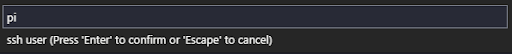
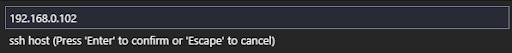
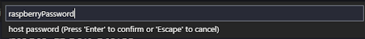
If you want to deploy the app through the SSH you can select the option “TotalCross: Deploy and Run” and then provide information about the SSH connection (User,IP,Password,Path). 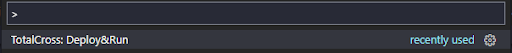

Conclusion
Now with everything built and deployed it is time for testing. Run the application on Android and the embedded system and start testing the Firebase communication and DHT11 data readings on the Home appliance application.
Feel free to edit, explore and use the TotalCross framework to tune up your embedded applications.
Code
Credits
TotalCross
TotalCross is an open source cross-platform framework developed to bring speed to GUI (Graphical User Interface) creation for embedded devices. TotalCross has the development benefits from Java without the need of Java running on the device, as it uses its own bytecode and virtual machine (TC bytecode and TCVM), created specifically for performance enhancement. TotalCross runtime is currently at 5MB to bring mobile grade user experience even for low-end MPUs.
Related products


Leave your feedback...