

How To Build A Pico Macro Pad

Made by raushan-kumar / 3D Printing / Art / Communication
About the project
hey, friends In this tutorial, I am going to show you How to Build a Macro Pad using Raspberry pi pico
Project info
Difficulty: Moderate
Platforms: Arduino, Raspberry Pi
Estimated time: 1 hour
License: Apache License 2.0 (Apache-2.0)
Items used in this project
Hardware components

Hand tools and fabrication machines
Story
hey, friends In this blog, I am going to show you How to Build a Macro Pad using Raspberry pi pico
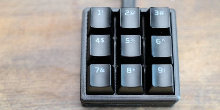
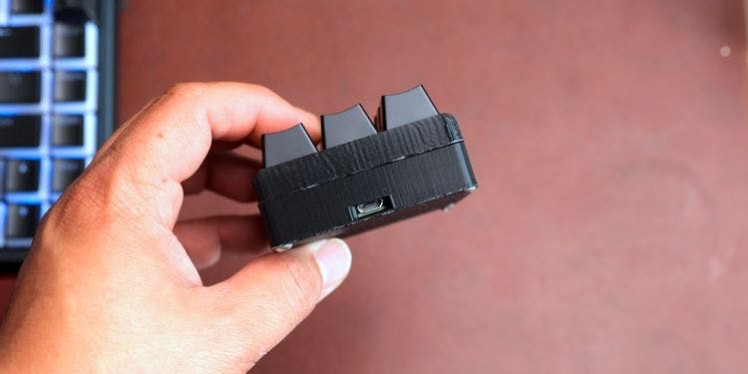
Pico KeyPad is a must-have shortcut keyboard for your PC work.
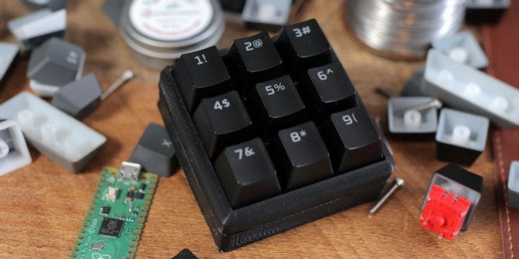
This keypad consists of 9 keys (you can add more no. of keys), the size of this 3x3 keypad is small and can be easily carried out.
All this 9 keys can be programmed for any shortcut. You can use it during programming / Coding or during editing and more, all the software shortcuts are compatible with this keypad.
In this written tutorial we a going to see how can we make it.
Thank You NextPCB:
This project is successfully completed because of the help and support from NextPCB. Guys if you have a PCB project, please visit their website and get exciting discounts and coupons.
Only 0$ for 5-10pcs PCB Prototypes https://www.nextpcb.comRegister
and get $100 from NextPCB: https://www.nextpcb.com/registerSee
more info about PCB Assembly Capabilities: https://www.nextpcb.com/register
Here are mid-summer sales at NextPCB :
1. Up to 30% off for the PCB orders
2. Up to 20% off for the PCBA orders
What Is a Macro Pad?
A macro pad is a series of buttons that allow you to trigger specific actions. Copy/paste is an excellent example of this type of function. If you press CTRL + C on your keyboard, this activates the copy shortcut and copies whatever you’ve highlighted to the clipboard.
Now, what if you could copy with only a single keypress?
What if you could trigger other actions, such as starting and stopping your Twitch stream? A macro pad lets you do that. What most people don’t know, however, is that these keypads are surprisingly easy to build, and the inexpensive Raspberry Pi Pico is the perfect microcontroller for the job.
Furthermore, once you know how these controllers are made, you can create a customized version that will put many commercial keypads to shame.
What Do You Need?
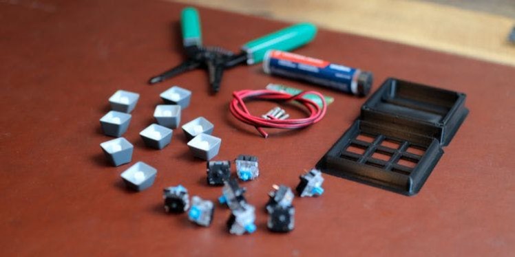
To create your own Macro Pad on a budget, you'll need to buy the following items.
1 Raspberry Pi Pico.
9 Gateron switches.
9 Keycaps.
A Soldering iron and soldering station.
1 Solder.
(4) M3 x 16 screws
.A 20 ga wire (about 2 feet).
1 Wire stripper.
A computer (for programming the Pico).
A case to put everything into.
A USB-C to micro-USB cable.
The most expensive part of this project is arguably the Raspberry Pi Pico. And if you have a 3D printer, you can save some money by printing the case and the keycaps yourself. Alternatively, you can have these printed for you instead; a selection of online options exist for these.
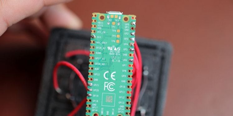
Raspberry Pi Pico GPIO Pinout
1 / 2
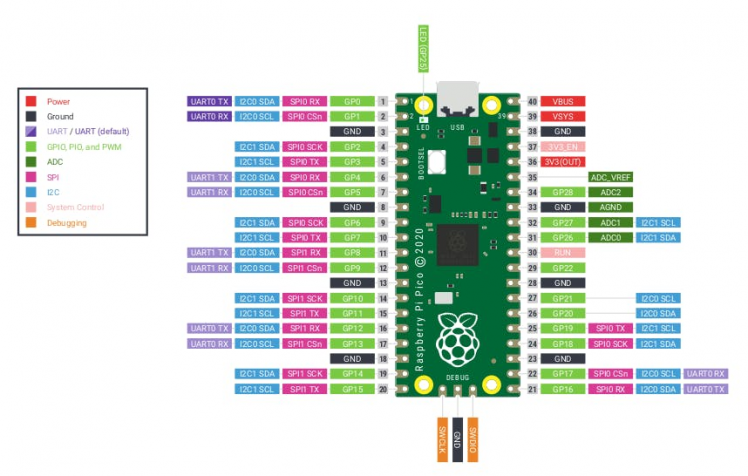
- 26 × multi-function 3.3V GPIO pins
- 2 × SPI, 2 × I2C, 2 × UART, 3 × 12-bit ADC, 16 × controllable PWM channels
- 8 × Programmable I/O (PIO) state machines for custom peripheral support.
- Castellated module allows soldering directly to carrier boards.
Operating at 3.3V, the Raspberry Pi Pico has a 40 pin GPIO, but it does not share the same form factor as the Raspberry Pis before it.
We have GPIO pins for digital inputs / outputs, pulse width modulation (PWM) and for specialist communication protocols such as I2C, SPI, UART/Serial. The GPIO also has three Analog inputs, something other Raspberry Pis lack, that use variable voltages to connect to, for example, a potentiometers, joystick or light-dependent resistor.
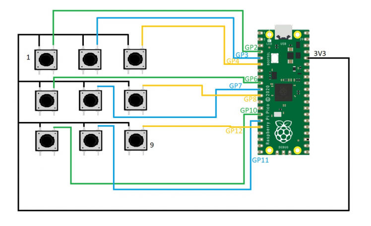
- Make all the connections as shown in the schematic diagram.
- Put the 3D-printed keys on top of the buttons using fast glue.
- fix the RPi Pico using some screws.
Once all of these connections are soldered, you’ve done the hard part! Now, it’s time to fire up your Pico and install CircuitPython.
How to Make Your Own Macro Pad

After gathering your materials, you’ll solder all of the electronics. Next, you’ll code the Pi Pico using CircuitPython, which will be a lot easier than it sounds. And finally, you’ll assemble the macro pad and set up your macros.
Ready? Let’s go!
Solder the Electronics
1 / 4

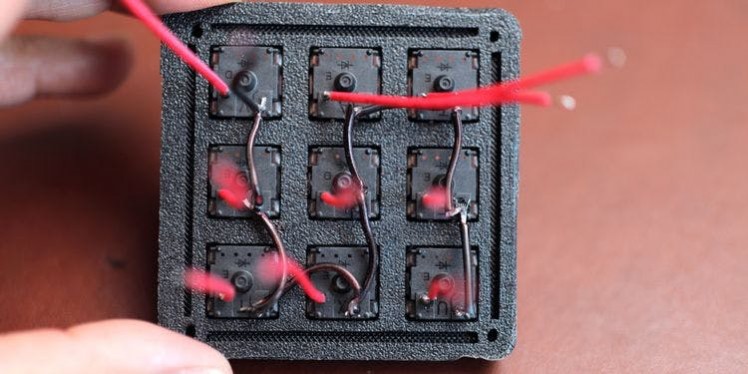
Start by installing the switches into the top portion of the case you printed, and then tin each switch’s electrical contacts. Solder a single short wire to each switch leg. We used one red wire and one black wire per switch, so the connections are easy to identify.
Disclaimer: If you’re not comfortable using a soldering iron or working with small electronics, you may want someone to help with this project. Soldering irons can reach temps of around 850 degrees Farenheit (450 degress Celsius), and misusing one can cause serious injury. Please be careful, and remember that you are responsible for your safety.
- Next, you’ll need to connect the switches in series. To do this, take the black wire from the upper left switch, trim it to length, and solder it to the second switch’s black wire location. Repeat this process with every switch until there is a single black wire connection running between the switches. When you’ve finished, you should also have one long black lead and nine red ones.
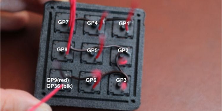
- Now, you’ll connect the Raspberry Pi Pico to the switches using the GPIO pins. Solder the red lead from each switch to a single GPIO pin on the Pi. Use the following pins and their corresponding switch locations as listed:
- Now, connect the remaining black lead from the last switch to GPIO36. This pin is your 3.3V out and will power the unit when the micro-USB cable is connected. Again, ensure that you use the 3.3V out—and not the 3.3V EN.
1 / 4
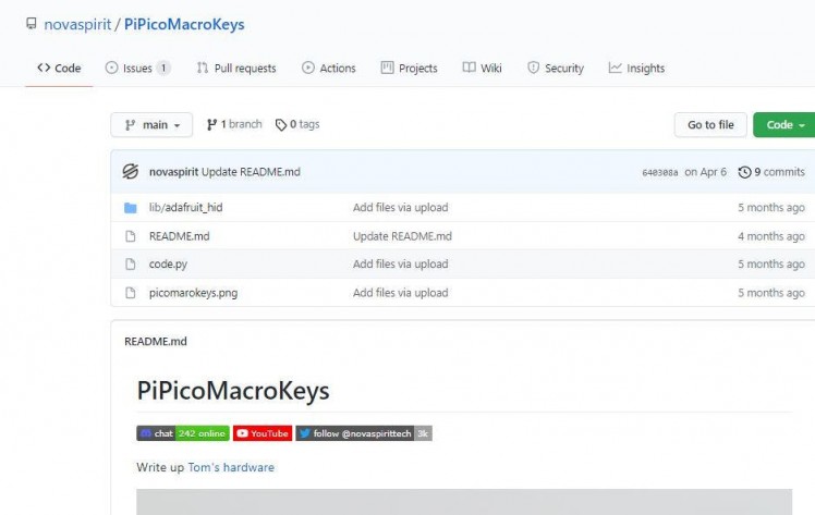
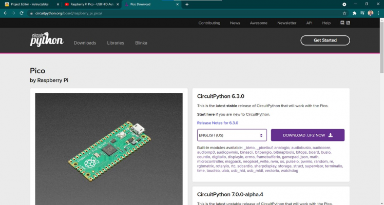

Before you connect your Raspberry Pi Pico to your computer, you should download the CircuitPython.UF2 firmware, this Novaspirit GitHub project, and a copy of either the Menu Editor or Thonny. Additionally, this build shows a configuration using a macOS computer. If you use Windows, the process should be similar.
To install CircuitPython, hold down the Bootsel button on the Pico and plug it into your computer using the micro-USB cable. You should see a new device pop up with the name RPI-RP2. That’s your Pico.
Next, drag the CircuitPython.UF2 firmware file to the Pico. Wait until the file finishes copying, then eject and reconnect the Pico. The device name should now appear as CIRCUITPY.
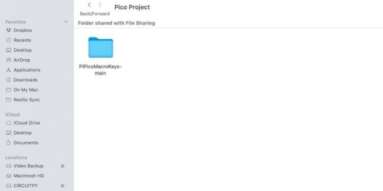
Now, unzip the Novaspirit Github project and drag the lib folder and code.py files from inside the PiPicoMacroKeys-Main folder directly into the CIRCUITPY root directory. This will install the libraries you need for the controller.
Next, click on CIRCUITPY. You should see a file named code.py in the root directory. Open this file with Mu Editor or Thonny.
Because Novaspirit’s original code.py file only offers six buttons, you’d typically need to make some adjustments for the extras. However, we’ve included a working code.py file below, so you don’t have to. Instead, copy and paste the entire code into the open code.py instance replacing everything else in the file. Then reboot your Pico.
# Originally coded by Novaspirit Tech
# Copy this code into your code.py file.
import time
import usb_hid
from adafruit_hid.keycode import Keycode
from adafruit_hid.keyboard import Keyboard
import board
import digitalio
# These are the corresponding GPIOs on the Pi Pico
# that you soldered
btn1_pin = board.GP1
btn2_pin = board.GP2
btn3_pin = board.GP3
btn4_pin = board.GP4
btn5_pin = board.GP5
btn6_pin = board.GP6
btn7_pin = board.GP21
btn8_pin = board.GP20
btn9_pin = board.GP19
btn1 = digitalio.DigitalInOut(btn1_pin)
btn1.direction = digitalio.Direction.INPUT
btn1.pull = digitalio.Pull.DOWN
btn2 = digitalio.DigitalInOut(btn2_pin)
btn2.direction = digitalio.Direction.INPUT
btn2.pull = digitalio.Pull.DOWN
btn3 = digitalio.DigitalInOut(btn3_pin)
btn3.direction = digitalio.Direction.INPUT
btn3.pull = digitalio.Pull.DOWN
btn4 = digitalio.DigitalInOut(btn4_pin)
btn4.direction = digitalio.Direction.INPUT
btn4.pull = digitalio.Pull.DOWN
btn5 = digitalio.DigitalInOut(btn5_pin)
btn5.direction = digitalio.Direction.INPUT
btn5.pull = digitalio.Pull.DOWN
btn6 = digitalio.DigitalInOut(btn6_pin)
btn6.direction = digitalio.Direction.INPUT
btn6.pull = digitalio.Pull.DOWN
btn7 = digitalio.DigitalInOut(btn7_pin)
btn7.direction = digitalio.Direction.INPUT
btn7.pull = digitalio.Pull.DOWN
btn8 = digitalio.DigitalInOut(btn8_pin)
btn8.direction = digitalio.Direction.INPUT
btn8.pull = digitalio.Pull.DOWN
btn9 = digitalio.DigitalInOut(btn9_pin)
btn9.direction = digitalio.Direction.INPUT
btn9.pull = digitalio.Pull.DOWN
keyboard = Keyboard(usb_hid.devices)
# below are the key values that you can change to
# fit your preferences. Change Keycode.ONE for example to
# (Keycode.CONTROL, Keycode.F4) for CTRL + F4
# on the first button.
# See the official CircuitPython docs
# for additional help
while True:
if btn1.value:
keyboard.send(Keycode.ONE)
time.sleep(0.1)
if btn2.value:
keyboard.send(Keycode.FOUR)
time.sleep(0.1)
if btn3.value:
keyboard.send(Keycode.SEVEN)
time.sleep(0.1)
if btn4.value:
keyboard.send(Keycode.TWO)
time.sleep(0.1)
if btn5.value:
keyboard.send(Keycode.FIVE)
time.sleep(0.1)
if btn6.value:
keyboard.send(Keycode.EIGHT)
time.sleep(0.1)
if btn7.value:
keyboard.send(Keycode.THREE)
time.sleep(0.1)
if btn8.value:
keyboard.send(Keycode.SIX)
time.sleep(0.1)
if btn9.value:
keyboard.send(Keycode.NINE)
time.sleep(0.1)
time.sleep(0.1)
This code is customizable and sends numerical inputs between one and nine, based on which key you press. Later, to change these functions, you’ll edit the (Keycode.ONE) portions of the code under the while True: section in the code.py file.
To do so, substitute whichever key you prefer for ONE. For example, you can use a single instance of (Keycode.customkey) or multiple, such as (Keycode.ALT, Keycode.TAB).
Finally, you’ll need to test the buttons. Open a text file and press the keys on your new keypad. They should return the corresponding numerical values between one and nine.
If everything is working, you can unplug the Pico from the computer and assemble the case.
Assign Your Macros
Now, you can assign specific actions to each key in programs like OBS or in the code.py file on the Pico itself.
In OBS, for example, navigate to Settings > Hotkeys and click on the Start Recording field. Then, tap one of your macro pad’s buttons. Click OK to save the macro. Now, try hitting that button. If you’ve set things up correctly, then OBS will begin to record.
Individual programs use different macros, so play around with your favorite software and see what fun shortcuts you can discover. Here’s a list of some things you might want to try:
- Assign a key to zoom in or out on webpages.
- Assign a key to the blade tool in DaVinci Resolve.
- Assign a “panic switch” that minimizes all windows in a single keypress.
- Assign a key to open the appointment dialog in your calendar.
- Assign a key to increase or decrease brush sizes in Photoshop.
- Assign a key to open Chrome.
- Assign a key to toggle fullscreen view in Twitch chat.
1 / 2

A macro pad or Stream Deck is helpful for improving your streaming or productivity workflows. But you don’t need to shell out hundreds of dollars to get great functionality. Instead, you can build an alternative with many of the same features.
Schematics, diagrams and documents
Code
Credits
Related products


Leave your feedback...