
Home Security System

Made by loik / Communication / Home Automation / Lights / Security
About the project
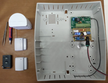
The system includes, apart from the home alarm board, our own RF transmitters in the form of remote controls for ease of use, magnetic switches for door and window protection, and a standalone RF RX module that is mostly used to adapt transmitters to other alarm systems, but can be used for home automation.
Project info
Difficulty: Moderate
Estimated time: 1 hour
License: GNU General Public License, version 3 or later (GPL3+)
Items used in this project
Hardware components

View all
Hand tools and fabrication machines
Story
The project is mostly centered around home security. We have an alarm board, the RF remote controls and magnetic switches (which can be used with any 24-bit encoding receiver), and a standalone RF RX board with 4 transistor outputs that is used to adapt our transmitters to other systems, but it is also used to replace/add remote controls to garage doors, control lights, and anything that you wish (we also have 2-relay adapter boards in case you need to drive something big).

The project was started decades ago by my father with the same ideas in mind, only recently have I remade all the board designs and microcontroller programs to allow for ease of build, use, bugfix and expansion, as the previous designs and programs weren't iterated on for a fairly long time (we literally lost the tech to make changes to the alarm board software code, as we couldn't recompile it). I have a programming background, I am actively learning the electronics part, I am also one of the people who builds and tests the boards, I am in contact daily with the people that install and mantain the systems in our clients' homes, which gives me a very good perspective of all angles I need to consider when I design the board and the code (maybe a bit too much, as I have churned out over 20 different versions between all the boards in less than a year).
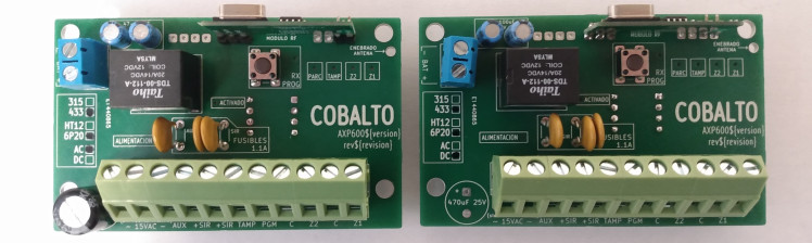
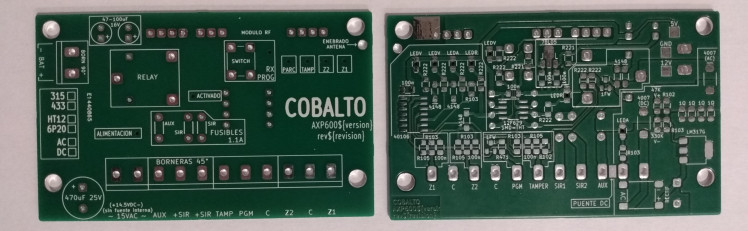
All our boards try to keep cost at a minimum without compromising usage, which is why we do not use 2 layer boards and try to reduce sizes as much as possible (mostly in the alarm board and RX module), and versatility in the case we need a different specification or we have to deal with components not being available (different RF module pinouts, SOP-8, SPP-14 or DIP-8 microcontrollers, reed switches or pre-wired magnetic switches, transmitter antennas in case we need more range and we can sacrifice aesthetics, etcetera).
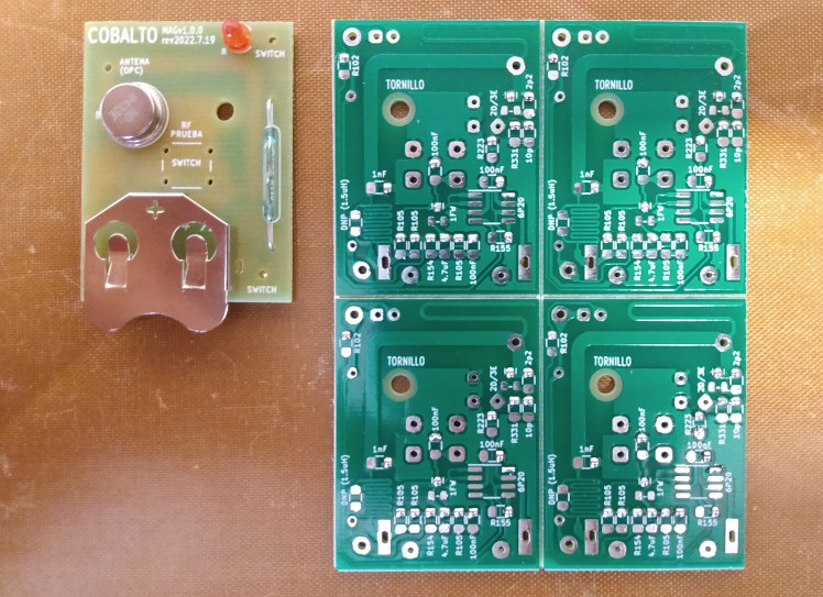
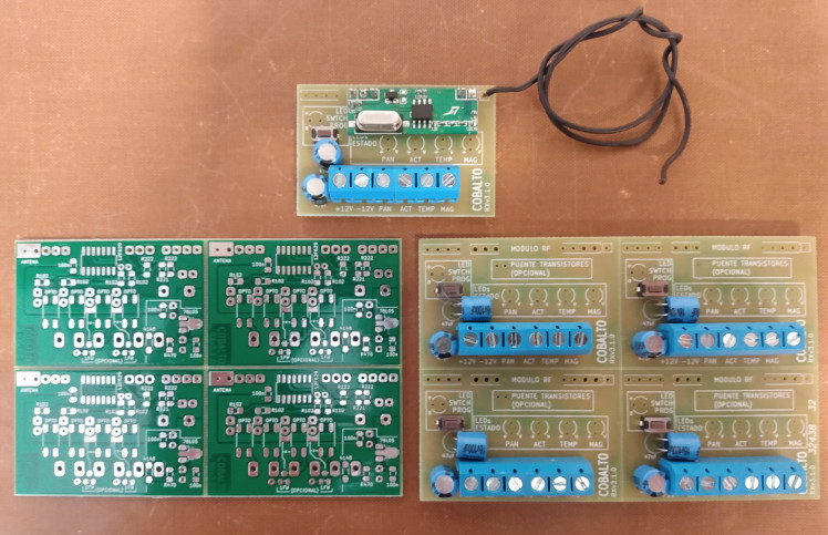
The alarm board functionality is relatively straightforward. It has 3 wired zones (anti-tamper, zone 1, and zone 2, which can be cancelled), 2 wireless zones (zone 1, which can be cancelled, and zone 2). It accepts any wired sensor and any wireless transmitter that works with 24-bit HT6P20 encoding. The remote control allows you to do a full activation, a partial activation, a panic button, and silent activation and deactivation. Activation and system trigger states are saved in the microcontroller's EEPROM, as well as learned transmitters. The only programming it requires after the board is built is learning the transmitters. It can be fed with 15-16.5V AC or 14.5V DC, depending on components placed.
We are also developing GSM communication for this board.
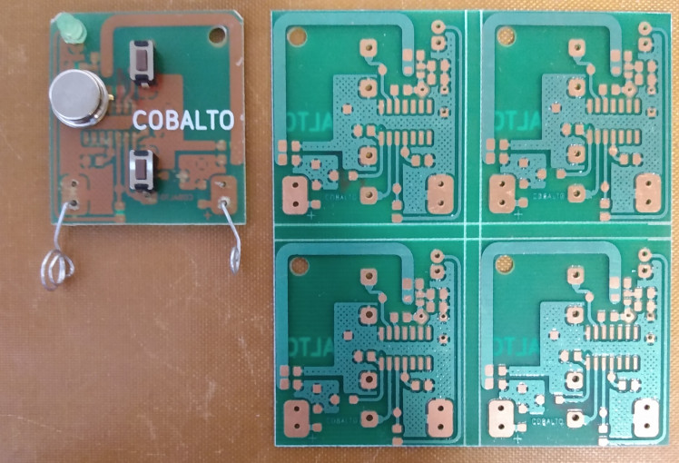
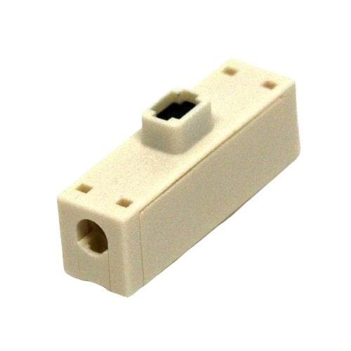
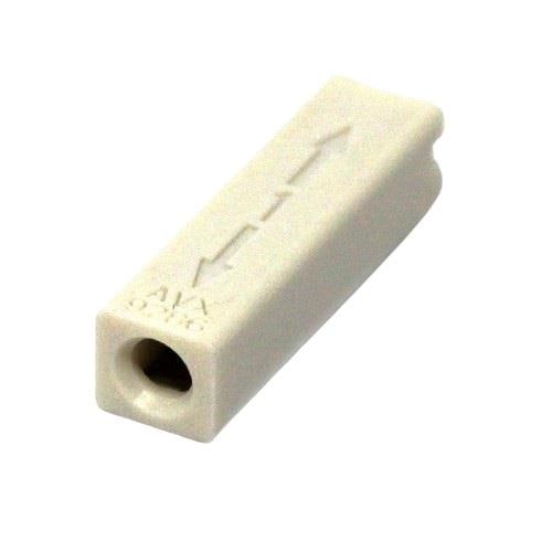
Our transmitters are the remote control and the magnetic switch. Our last remote control development gave us a range of around 100 meters in a busy city area by using a PCB printed antenna coupled with a capacitor to the PCB printed inductor (you will not see this in the pictures as I didn't have the prototypes at hand), which will allow us in the future to remove the need of an external antenna on our magnetic switches while providing excellent range.
These are designed with *mostly* 50 ohm impedance matching, as we haven't really needed to do impedance testing.
The RX module accepts any 24-bit encoding transmitter. The switch allows transmitter learning as well as changing output behaviour. You can change them between NC and NO, timed triggers and latch mode. These options as well as output states are saved in the microcontroller's EEPROM. It is fed with 12V DC.
I filmed a video of the alarm board functionality that I couldn't upload in time, as the boards arrived pretty much 24hs before the deadline due to customs issues as I also was outside of my city during the weekend (yes, I had to rush build them today :D).
All in all, thanks for the opportunity and, of course, the free boards we have received. They are really high quality. Special thanks to Rich, as he was the one who contacted me through Discord after he saw the pics of one of my prototypes that would make any electronic engineer gag, and all the people at EuroCircuits that were really helpful and willing to solve the problems I had.
Schematics, diagrams and documents
CAD, enclosures and custom parts
Code
Credits
Related products


Leave your feedback...