
Hc-12 Long Range Distance Weather Station And Dht Sensors

Made by Ron / Environmental Sensing / Sensors / Weather
About the project
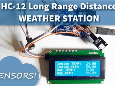
In this tutorial we will learn how to make a remote long distance weather station using two dht sensors, HC12 modules and the I2C LCD
Project info
Difficulty: Moderate
Platforms: Adafruit, Arduino, Visuino
Estimated time: 1 hour
License: GNU General Public License, version 3 or later (GPL3+)
Items used in this project
Hardware components

Story
In this tutorial we will learn how to make a remote long distance weather station using two dht sensors, HC12 modules and the I2C LCD Display.
Watch the Video!
Step 1: What You Will Need
1 / 7

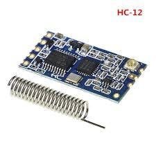
- 2X HC-12 Module
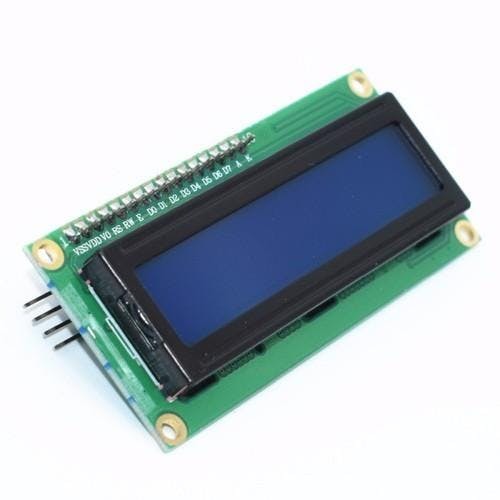
- I2C LCD Display 4X20
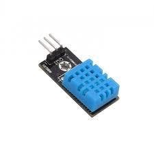
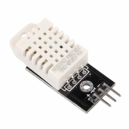
- 2 DHT sensors (In our project we use DHT11, DHT22)
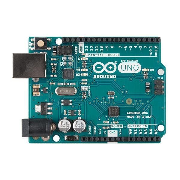
- 2X Arduino UNO (or any other Arduino)
- Breadboard
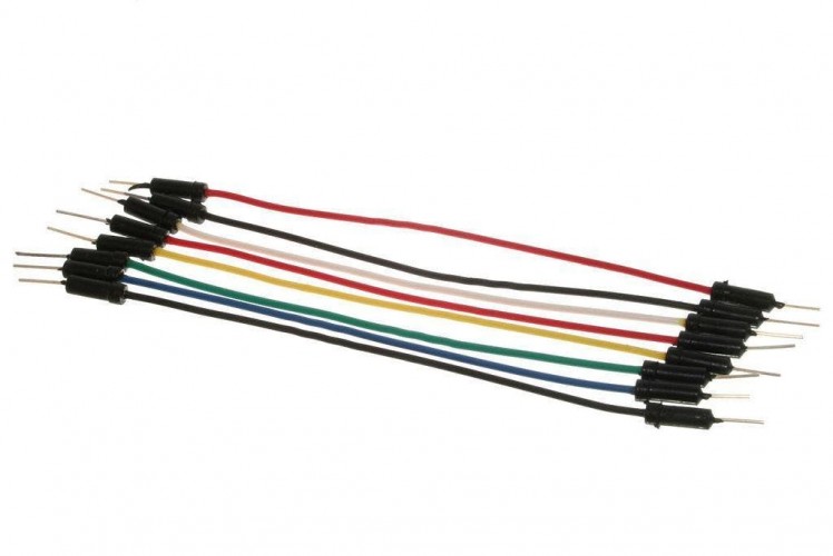
- Jumper wires
- Visuino software: Download Visuino
Step 2: Circuit - Sender
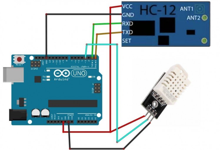
- Connect HC-12 pin [VCC] to Arduino pin [5V]
- Connect HC-12 pin [GND] to Arduino pin [GND]
- Connect HC-12 pin [TX] to Arduino pin [RX]
- Connect HC-12 pin [RX] to Arduino pin [TX]
- Connect DHT22 (or any other DHT sensor) pin Out to Arduino Digital pin 3
- Connect DHT22 pin VCC (+) to Arduino pin 5V
- Connect DHT22 pin GND(-) to Arduino pin GND
Note: Make sure that you disconnect the Arduino pin [RX] when you upload the code in Visuino, and after its uploaded reconnect it back.
Step 3: Circuit - Receiver
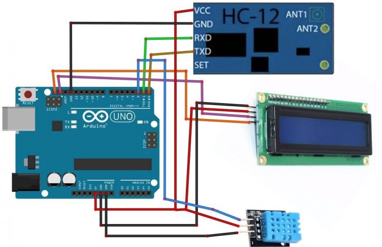
- Connect HC-12 pin [VCC] to Arduino pin [5V]
- Connect HC-12 pin [GND] to Arduino pin [GND]
- Connect HC-12 pin [TX] to Arduino pin [RX]
- Connect HC-12 pin [RX] to Arduino pin [TX]
- Connect LCD Display pin[VCC] to Arduino pin[5V]
- Connect LCD Display pin[GND] to Arduino pin[GND]
- Connect LCD Display pin[SDA] to Arduino pin[SDA]
- Connect LCD Display pin[SCL] to Arduino pin[SCL]
- Connect DHT11 (or any other DHT sensor) pin Out to Arduino Digital pin 2
- Connect DHT11 pin VCC (+) to Arduino pin 5V
- Connect DHT11 pin GND(-) to Arduino pin GND
Note: Make sure that you disconnect the Arduino pin [RX] when you upload the code in Visuino, and after its uploaded reconnect it back.
Step 4: Sender - in Visuino Add,Set & Connect Components
1 / 7
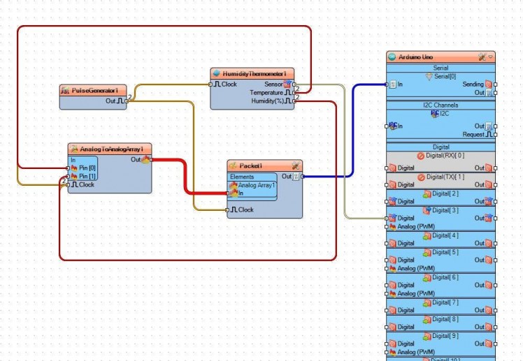

- Add "Pulse Generator" component and in the properties window set frequency to 5Hz
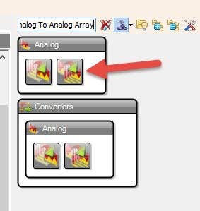
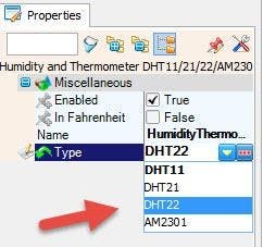
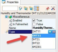
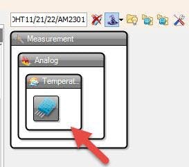
- Add "Humidity and Thermometer DHT11/21/22/AM2301" component, and in the properties window select the type, in our case its DHT22
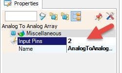
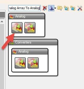
- Add "Analog To Analog Array" and in the properties window set Input Pins to 2
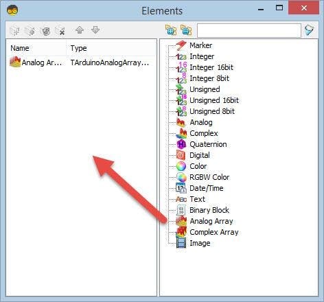
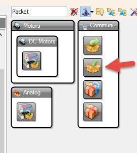
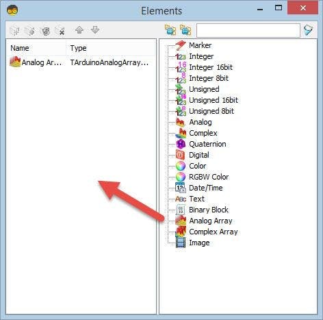
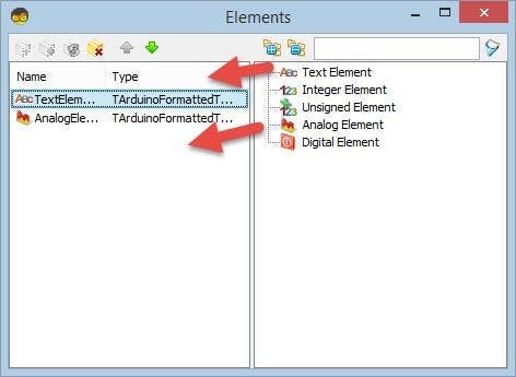
- Add "Packet" component, double click on it and in the Elements window drag "Analog Array" to the left side, then close the Elements window.
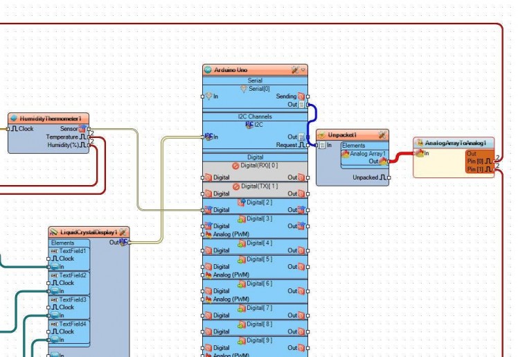
- Connect PulseGenerator1 pin Out to HumidityThermometer1 pin Clock and Packet1 pin Clock
- Connect HumidityThermometer1 pin Sensor to Arduino Digital pin 3
- Connect HumidityThermometer1 pin Temperature to AnalogToAnalogArray1 pin[0] and pin Clock
- Connect HumidityThermometer1 pin Humidity to AnalogToAnalogArray1 pin[1] and pin Clock
- Connect AnalogToAnalogArray1 to Packet1 > Analog Array1 pin In
- Connect Packet1 Pin Out to Arduino Serial[0] pin In
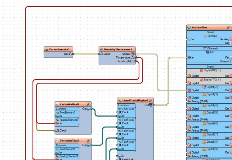
Step 5: Receiver - in Visuino Add & Set Components
1 / 16
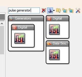
- Add "Pulse Generator" component and in the properties window set frequency to 5
- Add "Humidity and Thermometer DHT11/21/22/AM2301" component and in the properties window set Type (in Our case its DHT11)
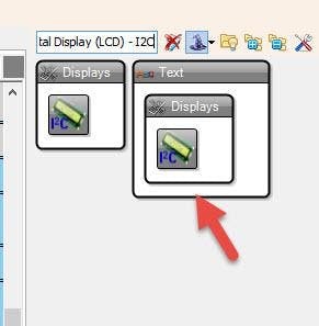
- Add "Liquid Crystal Display (LCD) - I2C" component and in the properties window set Columns to 20, Rows to 4
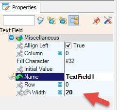
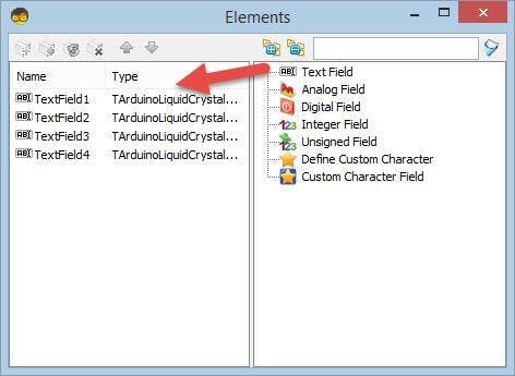
- Double click on the "LiquidCrystalDisplay1" and in the Elements window drag "Text Field" to the left side, and in the properties window set width to 20
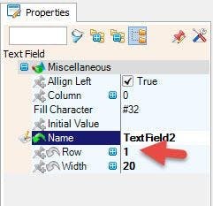
- In the Elements window Drag another "Text Field" to the left side and in the properties window set Row to 1 and width to 20
- In the Elements window Drag another "Text Field" to the left side and in the properties window set Row to 2 and width to 20
- In the Elements window Drag another "Text Field" to the left side and in the properties window set Row to 3 and width to 20
- Close the Elements window
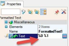
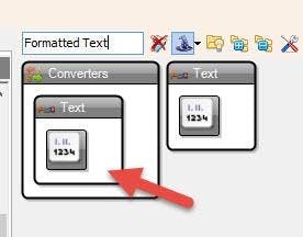
Add 4X "Formatted Text" component and for each in the properties window set Text to: %0 %1
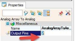
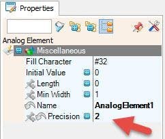
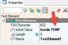
Double click on the "FormattedText1" and in the Elements window drag "Text Element" to the left side and in the properties window set Initial Value to: Inside TEMP: In the Elements window also Drag "Analog Element" to the left side and in the properties window set Precision to 2Close the Elements WindowDouble click on the "FormattedText3" and in the Elements window drag "Text Element" to the left side and in the properties window set Initial Value to: Out TEMP:In the Elements window also Drag "Analog Element" to the left side and in the properties window set Precision to 2 Double Click on the Unpacket1 and in the Elements window dragAnalog Array to the left sideClose the Elements windowClose the Elements windowAdd "Analog Array To Analog" component and in the properties window set Output Pins to 2
- Double click on the "FormattedText2" and in the Elements window drag "Text Element" to the left side and in the properties window set Initial Value to: Inside HUM:In the Elements window also Drag "Analog Element" to the left side and in the properties window set Precision to 2 Close the Elements Window
- Close the Elements Window
- Double click on the "FormattedText4" and in the Elements window drag "Text Element" to the left side and in the properties window set Initial Value to: Out HUM:In the Elements window also Drag "Analog Element" to the left side and in the properties window set Precision to 2Close the Elements Window
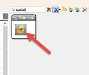
- Add "Unpacket" component
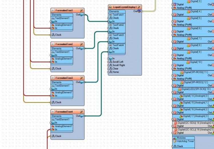
Step 6: Receiver - in Visuino Connect Components
1 / 4
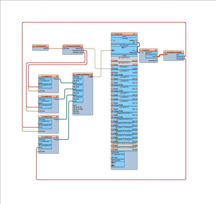
- Connect "PulseGenerator1" pin Out to "HumidityThermometer1" pin Clock
- Connect "HumidityThermometer1" Pin Sensor to Arduino Digital pin 2
- Connect "HumidityThermometer1" pin Temperature to "FormattedText1" > Analog Element1 pin In, and Pin Clock
- Connect "HumidityThermometer1" pin Humidity to "FormattedText2" > Analog Element1 pin In, and Pin Clock
- Connect Arduino Serial[0] pin Out to "Unpacket1" pin In
- Connect "Unpacket1" > AnalogArray1pin Out to "AnalogArrayToAnalog1" pin In
- Connect "AnalogArrayToAnalog1" pin [0] to "FormattedText3" > Analog Element1 pin In, and Pin Clock
- Connect "AnalogArrayToAnalog1" pin [1] to "FormattedText4" > Analog Element1 pin In, and Pin Clock
- Connect "FormattedText1" pin Out to "LiquidCrystalDisplay1" > Text Field1 Pin In
- Connect "FormattedText2" pin Out to "LiquidCrystalDisplay1" > Text Field2 Pin In
- Connect "FormattedText3" pin Out to "LiquidCrystalDisplay1" > Text Field3 Pin In
- Connect "FormattedText4" pin Out to "LiquidCrystalDisplay1" > Text Field4 Pin In
- Connect "LiquidCrystalDisplay1" pin I2C Out to Arduino pin I2C In
Step 7: Generate, Compile, and Upload the Arduino Code
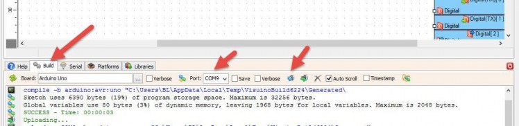
For both Sender and Receiver:
In Visuino, at the bottom click on the "Build" Tab, make sure the correct port is selected, then click on the "Compile/Build and Upload" button.
Very Important! Make sure that while you are uploading the code that Pin RX on the Arduino is disconnected and after the uploading connect it back.
Step 8: Play
If you power both Arduino UNO modules, the Display on the receiver will start to show the temperature andhumidity from both sensors. You can put the sender outside and you will be able to monitor Inside and Outside temperature.
Congratulations! You have completed your project with Visuino. Also attached is the Visuino project, that I created for this tutorial, you can download it and open it in Visuino: https://www.visuino.eu
Schematics, diagrams and documents
Code
Credits
Related products


Leave your feedback...