
Greenhouse Control System

Made by Al / Environmental Sensing / Garden / Plants / Sensors
About the project
IoT project to read environmentals viz. temperature, humidity and light, and control a water pump for irrigation, open/close ventilation windows via servos and operate a diesel heater. Water level and enviro info sent up to the Cloud on a regular basis e.g. 15 minutes. This is ideal for a greenhouse located away from Wi-Fi.
Project info
Difficulty: Moderate
Platforms: Nordic Semiconductor
Estimated time: 4 hours
License: GNU General Public License, version 3 or later (GPL3+)
Items used in this project
Hardware components


View all
Story
Please note that this is still 'Work-in-Progress' as the (fully-working) hardware needs to be controlled automatically from the sensors and I have to yet worked out the algorithms. Basically, the diesel heater will be controlled by temperature and the ventilation servos by humidity, but with some cross-coupling of data to reach optimum conditions for keeping the greenhouse plants happy.
Follow the instructions to load the software and generate a new app based on this:
asset_tracker_v2.
Make sure it works! I had to use NBIoT so the file prj.conf had to be modified such that line 45 now reads like this:
CONFIG_LTE_NETWORK_MODE_NBIOT_GPS=y
Add the ghouse.c file to the src directory. Add this line to CMakeLists.txt:
target_sources(app PRIVATE src/ghouse.c)
A few tweaks need to be added to main.c, but it is left relatively intact because ghouse.c simply looks like yet another task that the RTOS automatically starts running. The patches to add at line 40:
extern void ghmain(void);
/* size of stack area used by each thread */
#define STACKSIZE 1024
/* scheduling priority used by each thread */
#define PRIORITY 7
K_THREAD_DEFINE(ghmain_id, STACKSIZE,ghmain, NULL, NULL, NULL, PRIORITY, 0, 0); // fire up a new task APRW
That's all that you need to do, the Zephyr sorts it all out!
You may well discover the the graphs that appear on nRF Cloud have an incorrect time scale. There is a bug in which the CPU 'up-time' seems to be added twice with each timestamp, so the first reading is correct but the timestamp speeds off at twice the intended rate.
There is a bug-fix for this, but you need to apply the patch manually until such time as a new version is published. I am using V1.9.1. A link to the patch is on the Discord server.
How It Works!
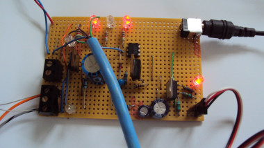
The Thingy91 has 4 NMOS transistor outputs. I have connected all the sources to 0V and added a piece of Cat-5 cable to feed the 4 drains and 0V to my interface board. Please add a piece of matrix board to the list of parts!
Output 1 controls a water pump, which was an old Peugeot's windscreen squirter. It has a capacity of 4 litres, and squirts at 40ml per second with 12V at about 4A. I have used an RFP30P05 PMOS FET for this job as it can easily handle that sort of current. The device is obsolete but I had some lying around.
For testing I am using a bench power supply, but its 2 amp output is not sufficient to run the pump so I have put a 12V 3.33A switch-mode mains supply in parallel with it. Without the SMPSU, the bench PSU's output drops to 8V at 2.2A and even though the pump continues to function, its flow rate is only 27ml per second.
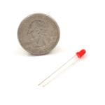
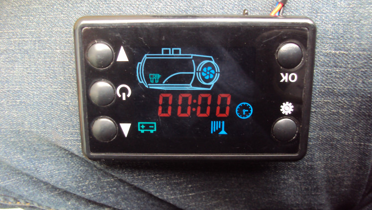
Outputs 2 and 3 control a diesel heater, but at the moment simply light LEDS fed off the 12V supply. I have yet to work out the heater controls. There is a 3-core cable between the front panel control board and the innards. I guess that the wires are 0V, 12V and a bi-directional digital bus like a single-ended RS485.
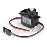
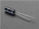
Output 4 controls servo motors. Radio control servos can be mounted on the windows so they can be opened and closed automatically. I have used 0 to 100 percent as the control, and the software in ghouse.c moves the servos at a rate of 10% per second. Both humidity and temperature can be used to open the windows, but I have not yet come up with the algorithm for this job. The interface board has a 6V regulator. An optocoupler generates the correct logic level for the servos. Current flow through the coupler's diode also discharges a capacitor C3 which powers up the regulator.
When the PWM stops, the capacitor C3 charges up via R7 thus switching off the servo power after a couple of seconds.
Power supply. The greenhouse has a large solar panel array which charges a large 12V lead-acid leisure battery. The 12V battery also powers the diesel heater. A relay is needed to prevent the heater from discharging the battery when heating is not required.
The Thingy91's battery can be kept charged via a 12V to USB converter.
Testing.
The Thingy91's main button is used to test the hardware. An RTOS timer is retriggered on each press of the button, and after 2 seconds, it times out. The timeout triggers a call-back which actions the test depending on the button count as follows:
1. Reset the water level to 4,000ml.
2. Turn on the heater.
3. Turn off the heater.
4. Move servos to 25% position.
5. Move servos to 50% position.
6. Move servos to 75% position.
7. Energise water pump for 4 seconds.
Other RTOS timers are used to time the water pump and switch off the servos once they have reached their demanded positions. A 100 millisecond sleep timer slowly changes the PWM value at 1 percent per loop to ensure smooth servo motion.
Small patches have been added to the existing asset_tracker_v2 code to send the water level to the Cloud.
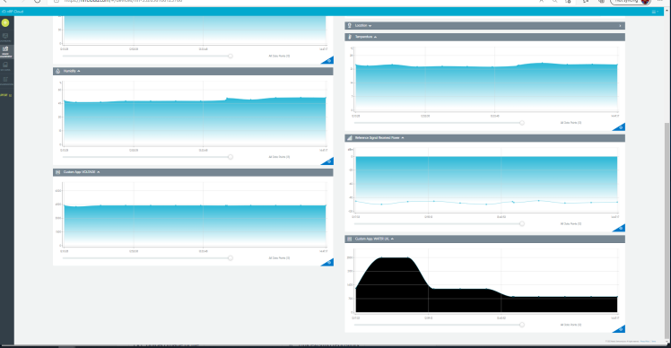
Here is the water level (bottom right graph) as displayed in nRF Cloud:
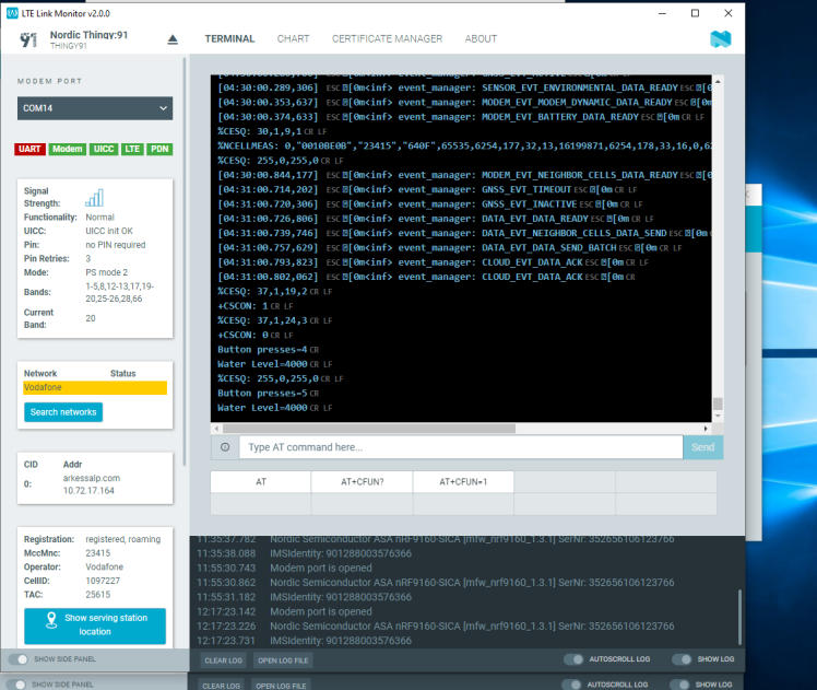
And here is the LTE Link Monitor, showing the Button presses and water level messages:
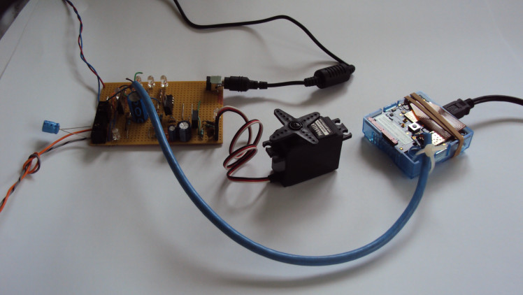
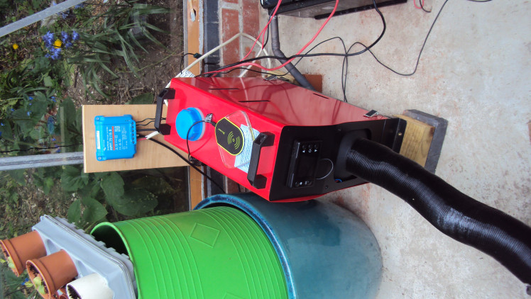
And the bits connected together...
The diesel heater control panel...
And the heater...
Test mode running...
And the water pump working...
Schematics, diagrams and documents
Code
Credits
Al
Been a keen radio amateur for many years. HF CW activity when I get the chance...homebrew radios and gadgets from valve amplifiers using EL84s etc in the past to a TV sound-bar using an Arduino and Class-D amplifier. I have been trying to build an electronic organ for a while but technology changes before I get anywhere!
Related products


Leave your feedback...