

Good Morning Sunshine: Automating Your Window Blinds

Made by mbparks / Environmental Sensing / Home Automation / Lights
About the project
Imagine automatic control of your window blinds based on the brightness outside.
Project info
Difficulty: Difficult
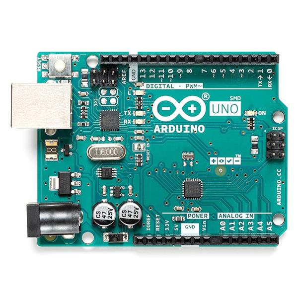
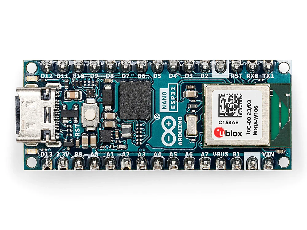
Platforms: Arduino
Estimated time: 2 weeks
License: GNU General Public License, version 3 or later (GPL3+)
Items used in this project
Hardware components


View all
Hand tools and fabrication machines
View all
Story
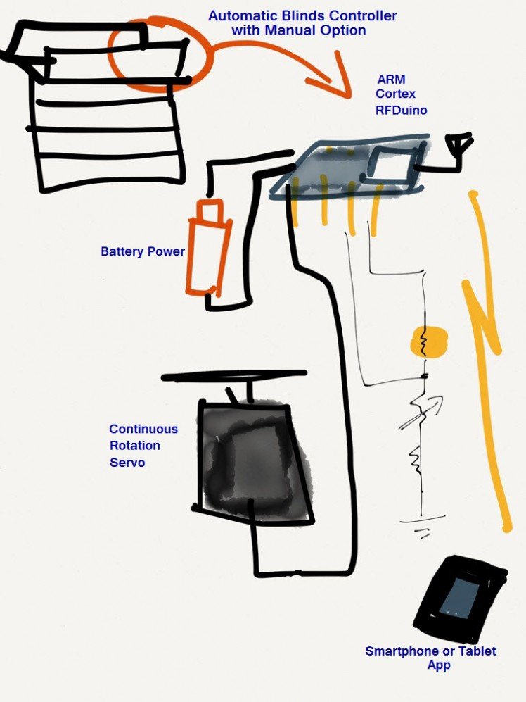
Overview
The goal of the project is to do a low-cost retrofit of existing windows blinds with a control mechanism that can be tucked away in the headrail. In my case I have inexpensive 2-inch faux wood slat blinds that can be found at your local home improvement store. With that in mind, we are going with a minimal bill of materials and through-hole components that can be used with perfboard.
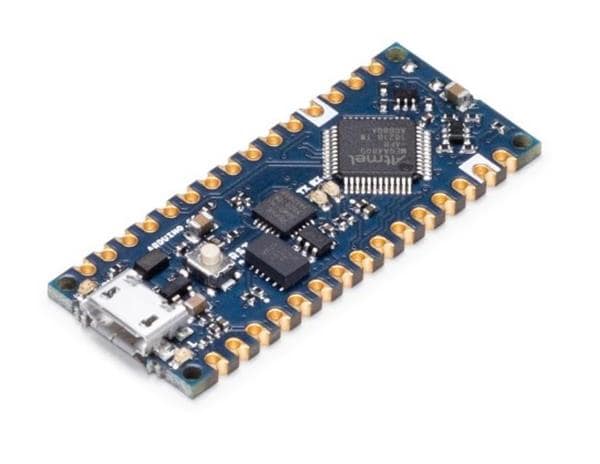
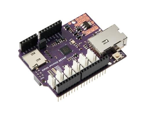
For the microcontroller, we’ve selected an Arduino derivative called RFduino. As implied, the RFduino contains an onboard radio, specifically a Bluetooth Low Energy (BLE) radio that allows for many interesting remote control applications with no need to use external hardware. Additionally, the RFduino is tiny, measuring a miniscule 0.90” (22.86mm) by 1.14” (28.95mm) while still providing seven GPIO pins. It is also equipped with male and female headers that allows stacking with similarly sized shields. For this project we’ll be using their prototyping board shield (P/N 975-RFD22125). Recall the headrail for the blinds used here are 2-1/4" (57mm) wide and 1-1/2" (38mm) deep.
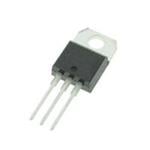
As for the additional components we are using an OSRAM photodiode optimized for visible light and a TI operational amplifier that can swing from rail-to-rail. These two components will let us monitor the intensity of the sunlight. We are using a servo to turn the blinds. Lastly, to power our circuit we are using a 9V battery along with a 3V and a 5V voltage regulator for the microcontroller and the servo, respectively. (Check the wiring colors of your servo, they can vary by manufacturer if you choose other than what is in the BOM.)
Lastly, to power our circuit we are using a 9V battery along with a 3V and a 5V voltage regulator for the microcontroller and the servo, respectively.
Building the Electronics
Here, we focus on soldering the project onto perfboard. Good engineering practice dictates that you should first test the circuit on a breadboard first. Also, when you are ready to solder up components be sure to experiment with placing the components first on the perfboard. You’ll want to print out the schematics for these before you start; a .jpg image file can be found in the Resources section.
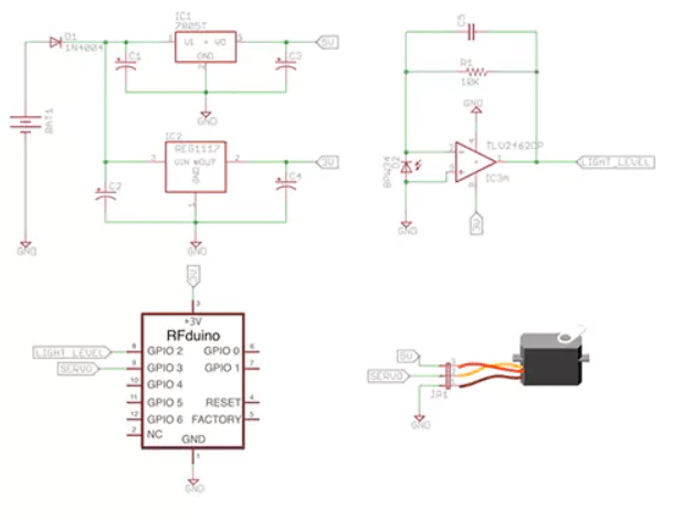
Figure 2: Schematic of the automatic blinds, showing all pieces.
Instructions:
1. Power Supply
- Place the two voltage regulators first towards the middle of your perfboard. Note that the TO packages of the 5V 7805 and the 3V 1117 voltage regulators are not the same! I assumed this incorrectly and was quite surprised by the immense amount of heat I felt from the 1117’s heat sink! I placed the two regulators with their heat sinks back-to-back, though not touching. This allowed me to tie together the inputs pins easily.
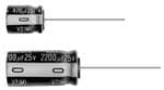
- Now place the 0.33uF capacitors near each regulator's input pin. Then place the 0.1uF capacitors across the outputs. Remember we are using polarized electrolytic capacitors so be sure to mind the positive and negative terminals.
- Add the reverse voltage protection diode to the inputs of the regulators, again minding the polarity.
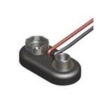
- Add the 9V battery terminal, with the positive lead (red) going to the input of the diode, and the negative lead (black) tying the ground connections of the all the capacitors and voltage regulators together.
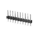
- Add four male header pins near the outputs of the regulators. One to the 5V output, one for the 3V output and two for the ground connection. One ground connection will be wired to the RFduino, the other to the servo.
2. Operational Amplifier Circuit
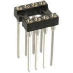
- Place the 8-pin IC socket onto the RFduino prototype board. Be sure to mind the Vcc and GND rails, and the GPIO pins. We went with a socket that can be used for wire wrapping if so desired. If not the extra long leads can be trimmed as desired. The socket provides convenience when making repairs should we accidentally fry the op amp.
- Now sit your op amp into the socket carefully. We are choosing to play pins 1-4 towards the middle of the prototype boards, since that is where most of our connections will be.
- We will pay male header pins at pin 2 and pin 3 since we will be placing the photodiode on a separate board. This will allows us flexibility in placing the photodiode depending on our particular blinds and window frame.
- Now let's place the feedback resistor and capacitor between pins 1 (output pin) and 2 (inverting input pin). You can take a deeper look at op amps in this Mouser blog post on op amps. For now, know that the resistor provides the feedback needed for the op amp to amplify the photodiode output voltage. By making it a trimpot we can manually tweak the sensitivity for our given setup and location. The capacitor provides protection from positive feedback messing with our circuit.
- Pin 3 also makes a connection to GND. I admittedly forgot this connection when moving from breadboard to perfboard. I erroneously thought I fried my op amp chip. Due to my flawed decision not to order multiple parts, I had to reorder the parts and lost of a few days during design. Ultimately I didn’t need the extra chips after doing some extra troubleshooting, but still a lesson was learned (or re-learned as it were). Always order at least one extra of each part, especially ICs, during the prototype phase.
- The output of the op amp, pin 1, will eventually get fed back to the analog-to-digital converter of the RFduino. For our purposes this will be RFduinio’s GPIO pin 1.
- Lastly, because it’s so easy to forget, connect the op amp Vcc and GND to the 3V and GND pin of the RFduino.
3. Photodiode
- There’s not much complexity with the photodiode. However, as with all diodes, be sure to mind the polarity.
- Solder the photodiode to the board and connect the leads to two male header pins. This will make it easy to wire up the diode back into our op amp circuit.
- The anode (+) lead of the photodiode will connect to pin 3 on the op amp.
- The cathode (-) lead of the photodiode will connect to pin 2 on the op amp.The cathode (-) lead of the photodiode will connect to pin 2 on the op amp.
4. Servo
- The power wire of the servo will connect to the 5V output of our voltage regulator board.
- The GND wire of the servo will connect to the GND of our voltage regulator board.
- The control wire of the servo will connect to GPIO pin 2 the RFduino.
Software
From a software perspective, this project breaks into two parts. First the code that runs on the RFduino, which:
- Controls the Bluetooth communications
- Takes an analog reading of the op amp’s output
- Controls the servo.
Second is the code that runs on a smartphone. For the manual mode, we are going to demonstrate an iOS app that lets you do rapid prototyping without having to write a custom app. This is in response to some feedback received from earlier projects. The first group of feedback has requested an iOS demonstration. Others were interested in devising a custom protocol for their project but didn’t want the hassle of developing their own app. So we are going to show that it’s possible to do prototyping with iOS and there apps that you can customize on the fly to meet your needs.
RFduino Code
As of the time of this article, the RFduino was only compatible with Arduino IDE 1.6.3 offered by arduino.cc. Head over here to download that version (https://www.arduino.cc/en/Main/OldSoftwareReleases#previous). If you have suggestions, please use the comments section associated with this project.
The RFduino folks offer a great set of tutorials on setting up the Arduino IDE to support the RFduino, you can find them here: http://www.rfduino.com/product/rfduino-brief-intro/index.html
Some highlights from the code:
- #include lets us adds libraries into our projects. This promotes code re-use, unless you have very specific needs, re-inventing the wheel is not necessary.
- #include
will let us control the servo easily. This library lets us control the angle of rotation of the servo. - #include
gives us the ability to use the full feature set of the RFduino hardware, including the Bluetooth Low Energy radio. - #define the constants. Constants are like variables, except they will never change their value. Defining numbers as a constant makes your code more readable.
- #define lightSensor 2: The output of the photodiode op amp will connect to pin D2 of the RFduino.
- #define servoPin 3: The control pin of the servo will connect to pin D3 of the RFduino.
- Some Key Variables: These are variables you might want to tweak depending on your particular design choices.
- float lightThreshold = 100.0: This floating point number represents that cutoff point between light and dark. If the light we are measuring with the photodiode exceeds this number, we open the blinds. If we measure less than this value, we close the blinds.
- int blindsOpen = 80: The angle we rotate the servo to cause the blinds to open.
- int blindsClose = 10: The angle we rotate the servo to cause the blinds to close.
- Overview of the Key Functions
- void setup(): The setup loops initializes the servo, the serial communications for debugging purposes, and the Bluetooth radio.
- void loop(): This is the main loop. All it does is check to see if it is in automatic mode (meaning it should open and close the blinds based on the ambient light). If it is, take an analog reading from the photodiode circuit, and make a decision to open or close the blinds.
- void RFduinoBLE_onReceive(char *data, int len): Waits to hear for an incoming byte from the a smartphone and depending on the character received, take a an action. These include:
- “A”: Enter into automatic mode.: The angle we rotate the servo to cause the blinds to open.
- “B”: Enter into manual control mode:
- “C”: Open the blinds
- “D”: Close the blinds
- boolean rotateBlinds(int position): Rotates the blinds to the angle that is defined by the input int position.
Arduino Manager iOS App
In previous project we’ve written custom Android apps using MIT App Inventor. This project we are taking a slightly different route in using an iOS app that is specifically geared towards Arduino prototyping. The app is called Arduino Manager and can be found the App Store, you can find it here: https://itunes.apple.com/us/app/arduino-manager/id497240094?mt=8 . I will point out that the app, after in-app purchases will run you $20. That can be a deal killer for many, but if you are planning to do a lot of projects with Arduino, Bluetooth, and iOS, then this is worth the upfront investment.
Here are the steps I used to setup the buttons to control the blinds.
Note the since the RFduino is Bluetooth Low Energy, this will require you to run on an iPhone 4S or newer. Likewise, if you decide to stick with Android, you will need to make sure your phone is Bluetooth LE compatible.
Assembly
Since the headrail of blinds tends to be metal, we designed and printed some small plastic pieces to help insulate our components. We also printed a small coupler that can be attached to the central rod of the blinds rotation mechanism and the servo arms. The 3D files to create these yourself are in the Resources section, however, none of this is absolutely necessary; electrical tape can substitute for the plastic components. A bit of hot glue will connect the servo to the rotation mechanism just fine, I did it with no problem during development.
The only required modification to the blinds themselves is to remove the manual control mechanism and string. To do so, remove a headrail end cap from either end of the blinds. Then pull the central rod out a bit, which will free the manual control mechanism with no trouble, then simply pull the string through the hole and you are ready to add your new electronic controls.
I found that placing the 9V battery and the regulator board toward the middle of the headrail works best. Then running the POWER and GROUND wiring to the end of the headrail where the servo and RFduino are located. I did have to remove the mounting mechanism built into the servo case with a pair of tin snips and then sanding down the remainder. Lastly, I inserted the RFduino with the antenna facing towards the END CAP of the blinds.
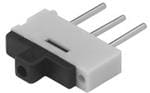
If I were to refine this project I would look to see if I could get the entire project, battery included, into an enclosure that could fit completely in the end cap of the headrail. Additionally, I might consider a physical on/off switch (which has been added as optional to the BOM.) I would add it in between the positive terminal of the battery lead and the input to the voltage regulator circuit.
All 3D parts are optional, including the coupler part. You can simply hot glue a servo arm directly to the rotation mechanism in the blinds. It is surprisingly straightforward once you take a look at how they work. If you choose larger blinds, you may want to consider the mechanical aspects (e.g. the torque needed to open/close).
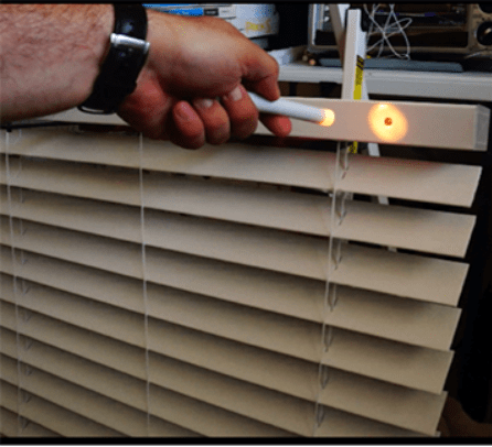
Project In Action
The control mechanism is pretty straightforward. Simply fire up the app that we set up previously and connect the RFduino.
Connecting
To connect for the first time simply select the Menu icon in the bottom left of the app and then press the "Connections" button. With your circuit powered on, press the "Scan BLE" button and it will find you RFDuino which you will then select. Once connected press "Close" and you will return to the screen with the buttons you created earlier. You only need to do these steps once. After the initial setup to connect over BLE, you simply press the icon of the Arduino at the bottom of your screen and the app will now connect to your RFduino.
Send the command to enter in manual control. Then try opening and closing the blinds using the buttons we setup in the app. Next, set it back to automatic mode and try covering the photodiode with your hand. Verify that the blinds are opening and closing. Remember to tweak the variables in the code as needed.
Keep in mind the following when finally testing your finished project:
- I have setup the hardware and software to initiate in the closed position and in automatic control mode, meaning the blinds will open and close based on the brightness of the ambient light.
- Tweak the rotation variables if your servo continues to make noise after reaching the desired open and closed position.
- Originally I had planned to use a continuous rotation servo thinking I would need multiple revolutions to complete a single open or close action. Turns out this is not the case and standard servo with 180 degree of rotation works fine.
Credits
mbparks
Mike Parks is the owner of Green Shoe Garage, a custom electronics design studio and security research lab located in Southern Maryland. He produces content for the Gears of Resistance which shares news and tips for those interested in the maker movement, open-source hardware and software, STEAM education, citizen science, and digital citizenship. He is also an extra class ham radio operator, a licensed Professional Engineer in the state of Maryland, and most notably a dad.
Related products


Leave your feedback...