
Geoleaf - 3d Printable Geometric Lights With Alexa & Hue

Made by DIY-Machines / 3D Printing / Art / Lights / Retro Tech / IoT
About the project
Customisable low cost & 3D printable smart geometric light panels which connect to Hue and Alexa to brighten and personalise a space.
Story
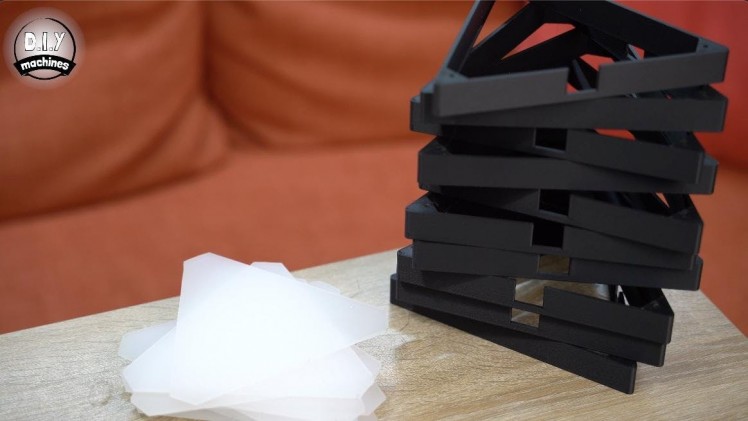
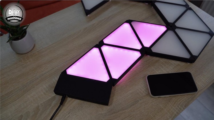
Meet Geoleaf, my low cost and 3D printable version of Nanoleaf lighting panels.
I have wanted some Nanoleaf lights for a long time but the price has always been too high for me. So I thought I would set about creating my own version using a 3D printer. Each lit panel works out at about £3.40 in materials to make and I’m very happy with the end result.
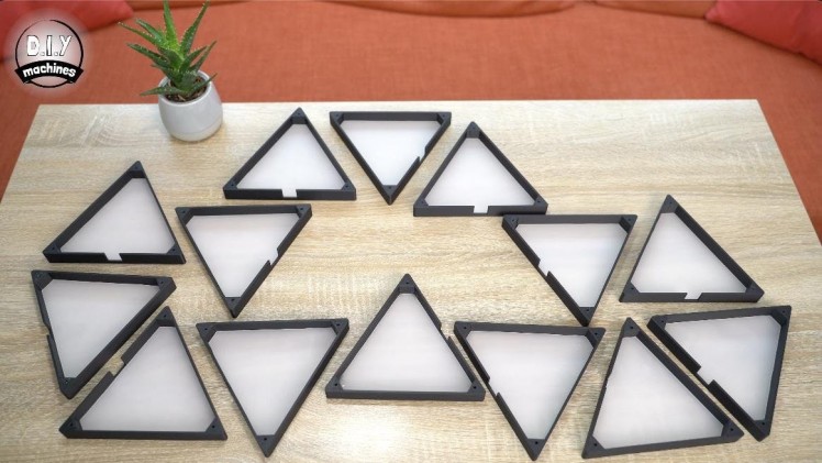
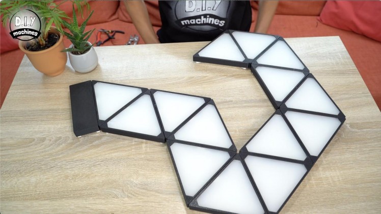
You can assemble them in any order to suit your wall space and other shapes can be included such as the optional square panels. I have offset them from the surface to allow a stylish glow out across the wall in the evenings and the panels themselves are bright enough to be seen in the daytime.
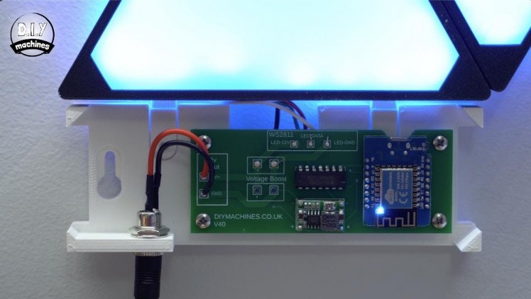
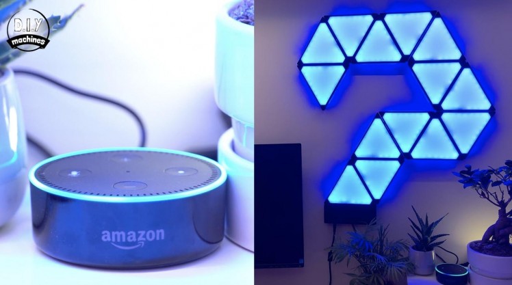
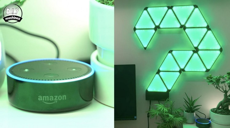
I’m using an ESP8266 to control them using the brilliant WLED firmware and its built in webserver. The smarts for the project are all housed in the discreet rectangular panel at the bottom. They can also be programmed to automatically mimic a Phillips Hue bulb or respond to Alexa commands.
I’ll share with you now how I made them - they’re really rather simple.
Step 1: Project Video
For those of you who prefer to watch something instead of reading I have created a detailed tutorial video. Don't worry though, everything in the video (and a little more) is all explained in this tutorial. Though, even if you will read through this guide I highly recommend looking at the introduction in the video to get an idea of the effect the lights achieve. :)
Step 2: Bill of Materials / You Will Need
1 / 3


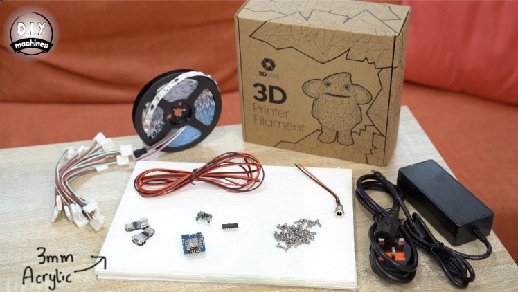
To build your own version of Geoleaf you're going to need just a few items and tools. None of these should be too tricky to find and I have included links to where you can find the items online:
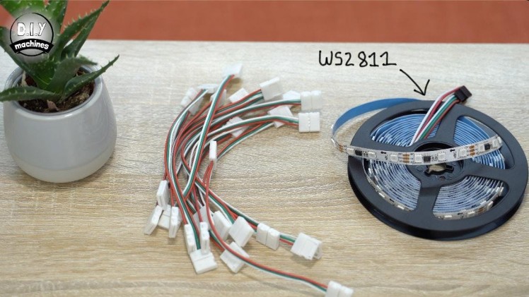
- 12v WS2811 LED’s (A 5 meter roll is enough for 12 panels): https://geni.us/WS2811-60
- 10mm LED connectors - one per panel: https://geni.us/3Pin10mmLEDCable
- 3D Printer Filament: https://geni.us/3DJake
- Acrylic sheets (1 A4 sheet = 3 triangles): https://geni.us/OpalFrostedA4Acrylic
- DC to DC Buck converter (Mini 360): https://geni.us/Mini360
- Logic Level Shifter (74AHCT125): https://geni.us/74AHCT125-LLS
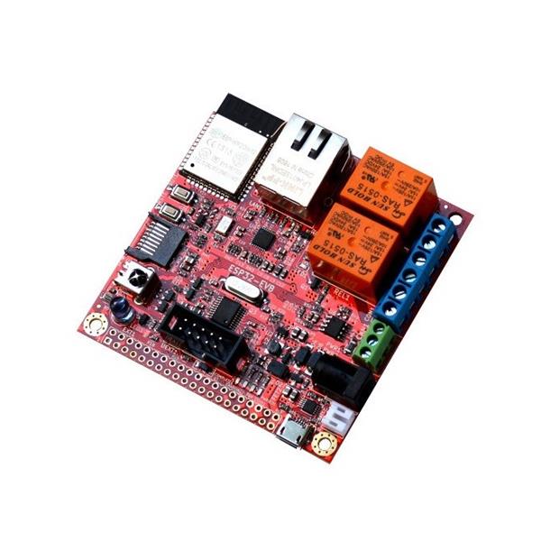
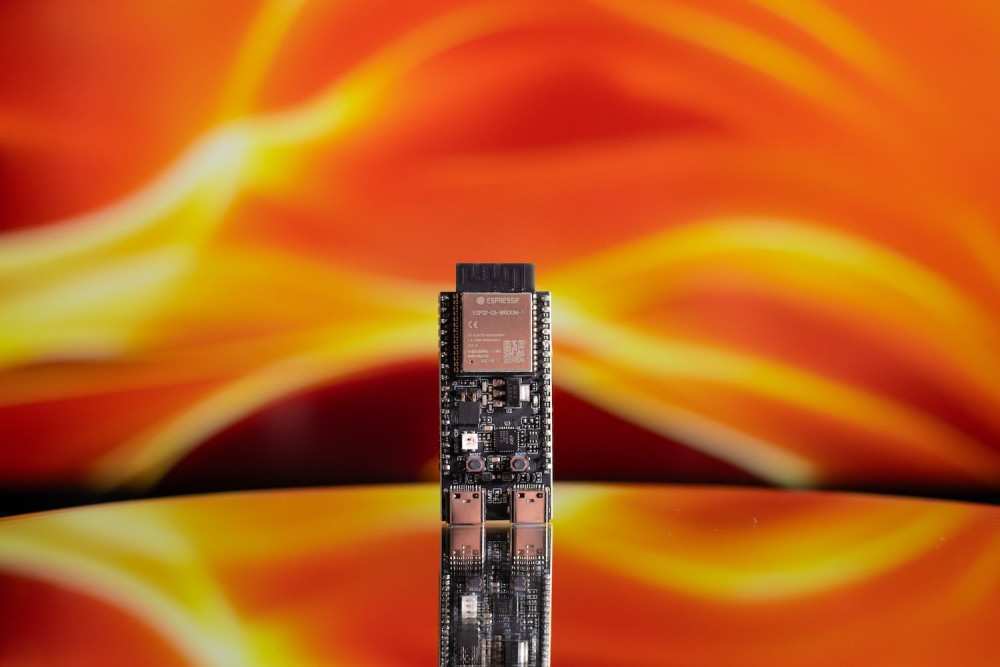
- ESP8266 Dev Board: https://geni.us/wemosD1
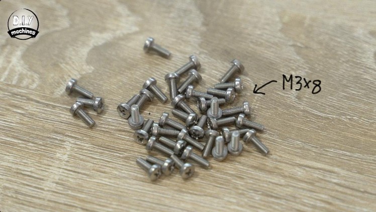
- Plenty of M3x8 bolts: https://geni.us/NutsAndBolts
- Barrel connector suitable for at least 5amps https://geni.us/HighAmpDCBarrel
- 12v Power Supply (6 amp+): https://geni.us/12VPowerSupply6A
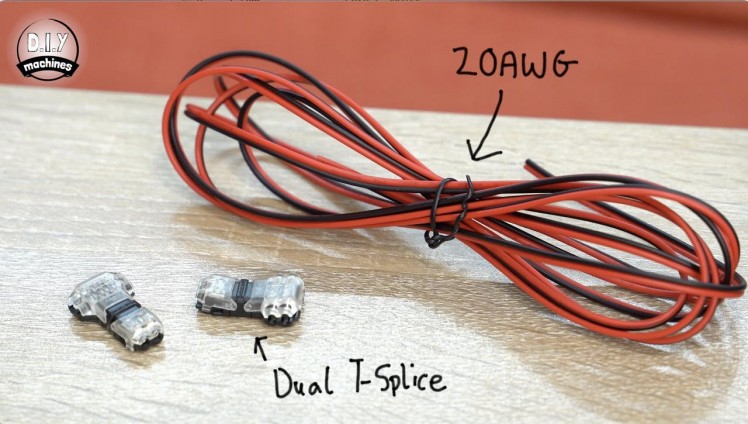
- Dual T splice connectors (x2): https://geni.us/DualTSplice
- Some 20AWG wire (0.8128mm in diameter): https://geni.us/20AWG
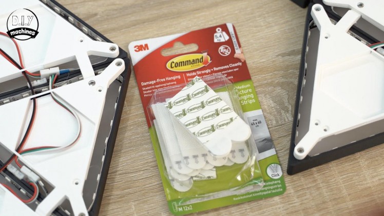
- 3M Command Hanging Strips: https://geni.us/CommandStrips
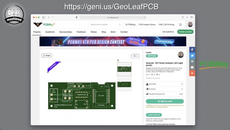
There are two different options for connecting the electronics together for this project. I learnt how to design a PCB for this project and have uploaded the design to PCBway where you can order a PCB of your own for just a few dollars/pounds. This is the simplest way to assemble the electronics:
- Projects PCB: https://geni.us/GeoLeafPCB
Or optionally you can use a piece of Adafruit PermaProto board to connect everything along with some wiring connectors for the higher current connections. You will find details of both methods later in the instructions
- PermaProto Board: https://geni.us/HalfPermaProto
- Wago Connectors: https://geni.us/Wago221
Step 3: Printing the Triangles - Walls
1 / 2
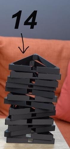
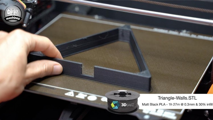
The first thing we need to print are the sides of our triangles. The file for this is attached 'Triangle-Walls.stl'.
I printed mine in 3D Jakes ecoPLA Matt Black as I wanted it to contrast with the grey walls in my home office but you can use a different color if you prefer. As I will be using fourteen illuminated triangles in my end design I will print fourteen of these 'walls'.
My print settings were:
- 0.3mm layer height
- No supports
- No brim
- 30% infill
This resulted in a print time of roughly 1 hour 27 minutes per panel.
If you would like to add in some square illuminated panels than you can find the optional files for the squares here on Etsy: https://www.etsy.com/uk/listing/1067981962 . The donations received through people buying the files for the optional square panels helps to fund the next project I am working on - but please note this is optional and not necessary to complete the project. 😊
Step 4: Cutting the Acrylic
1 / 6
For this step you will need:
- Acrylic sheets
- Saw
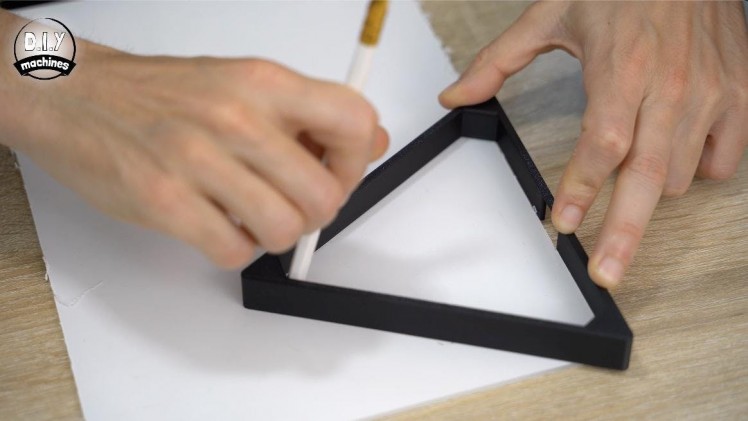
- Pencil
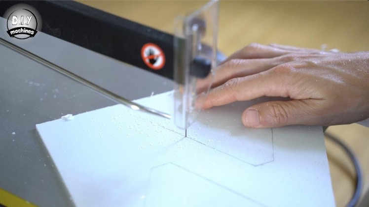
I am using some 3mm thick opal acrylic to diffuse the light for this project. I purchased some A4 sheets which we can cut three panels worth of acrylic diffusers from. My fourteen triangles therefore required five A4 sheets.
You can use a pencil to mark on the sheets (don't remove the protective film from them yet) an outline of the shape we need to cut. To do this, take one of your 3D printed triangular walls and place it onto the acrylic sheet so that the holes for the bolts is facing downwards. You can then trace the inside of this shape.
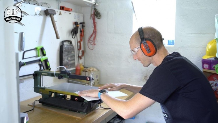
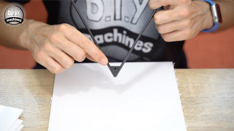
There are several ways that you can cut a sheet of acrylic, such as scorring and then snapping, hot wires or saw blades. This is beyond the scope of this tutorial for me to go through the pros and cons of each method.
I decided to cut mine with a fret saw. A hand saw or similar would work just as well. Once you have cut the shapes you can test there fit inside one of the triangles which will then allow you to trim any excess off before you remove the protective films from both sides of each of the panels.
Step 5: Gluing the Acrylic
1 / 4
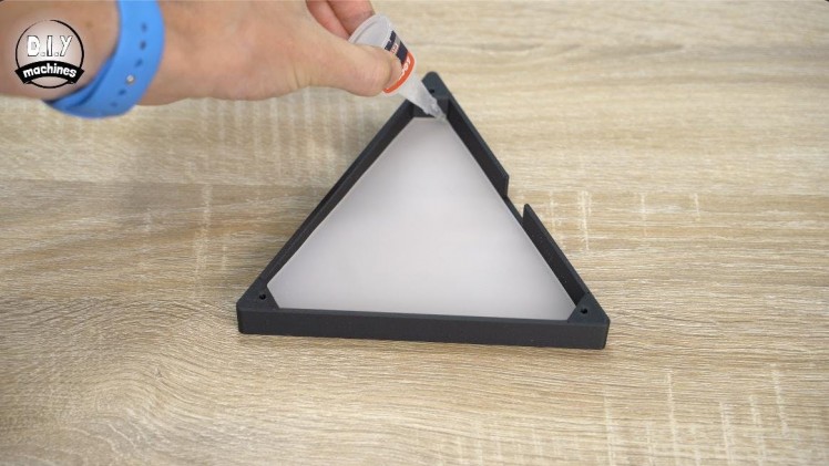
For this step you will need:
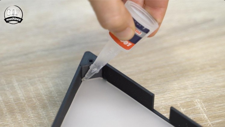
- Super Glue
Once they have all been cut, checked to fit properly, and had their protective films removed you can then set about gluing them into place inside of the triangles. To do this, push fit the acrylic and then check you are happy with the fit when viewed from the front. If so, turn it back around and use some generous dabs of super glue in the corners. Repeat this for all of your triangles before allowing them some time to cure before continuing to work with them.
Step 6: Preparing the LEDs
1 / 9
For this step you will need:
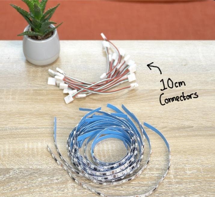
- WS2811 12v LEDs (supplied on a roll)
- 3 Pin 10cm Wire Connectors
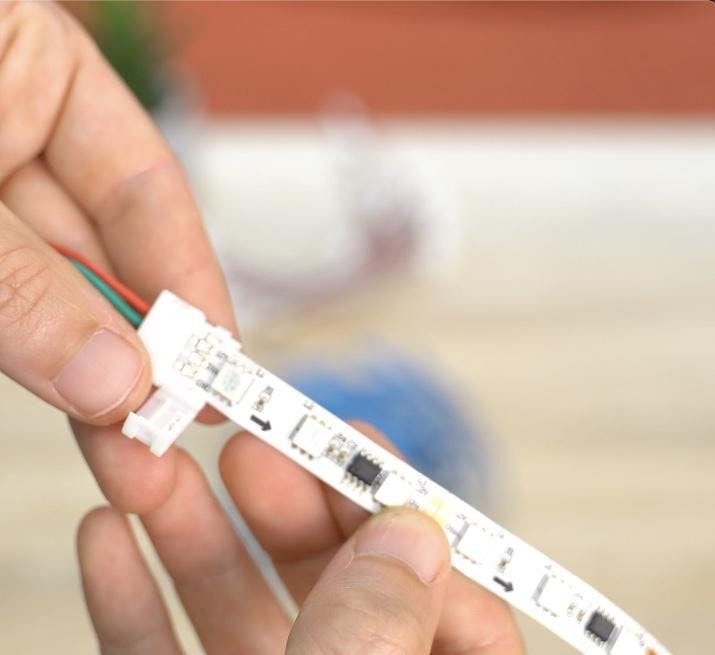
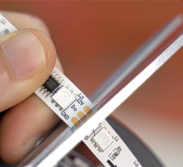
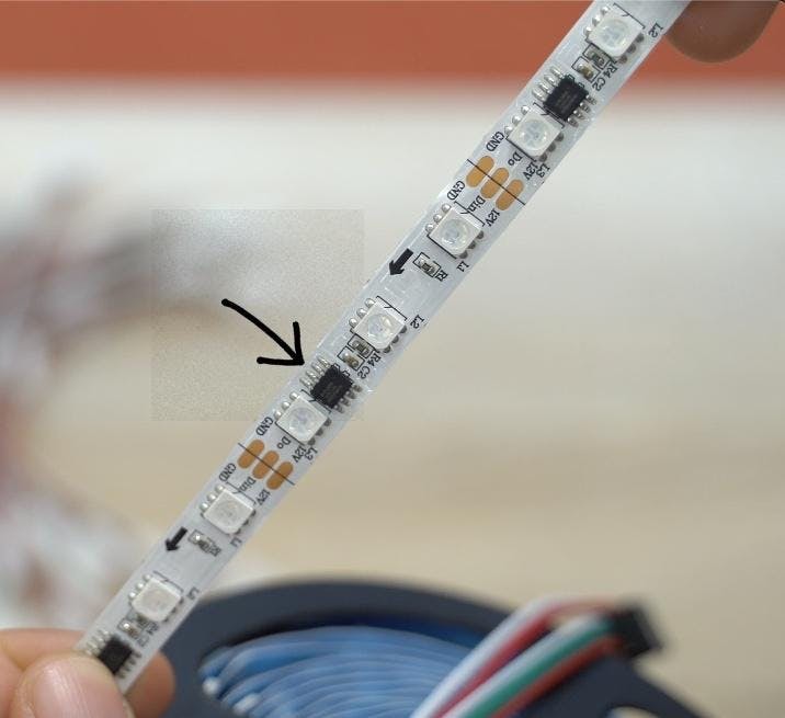
Unlike the more commonly used Neopixels/WS2812B LEDs the WS2811 LEDs which we are using have one controller (black integrated circuit package) for every three LEDs. Because of this please pay close attention to where you can cut the strips every three LEDs.
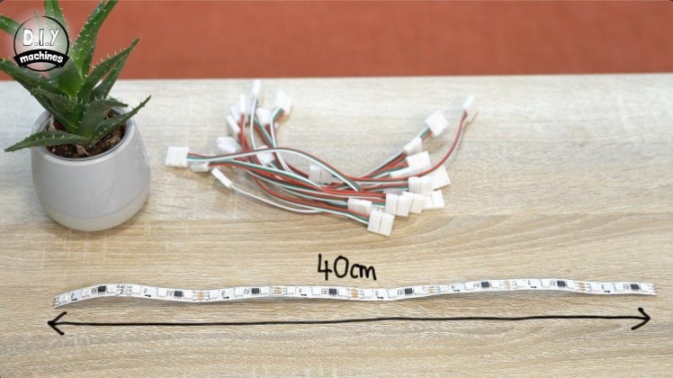
Each of our triangles will require about 40cm worth of LEDs which works out as having 8 segments of three LEDs on each strip.
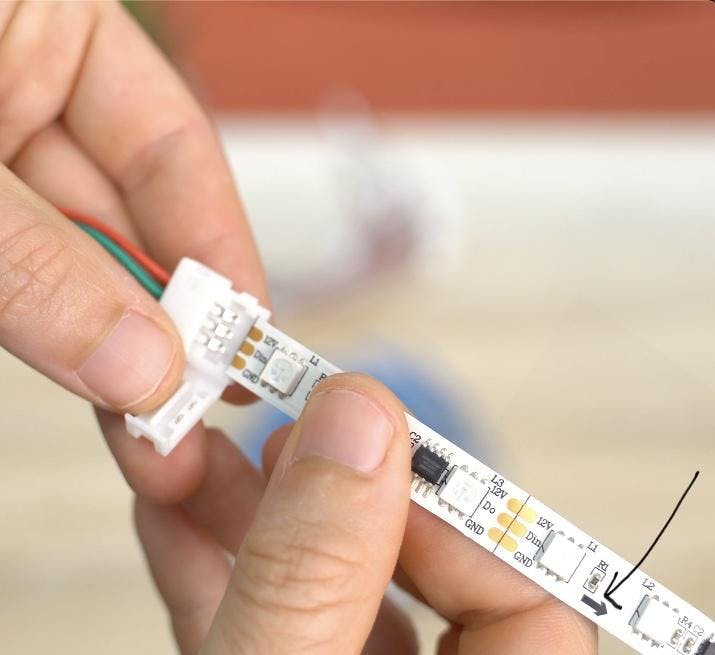
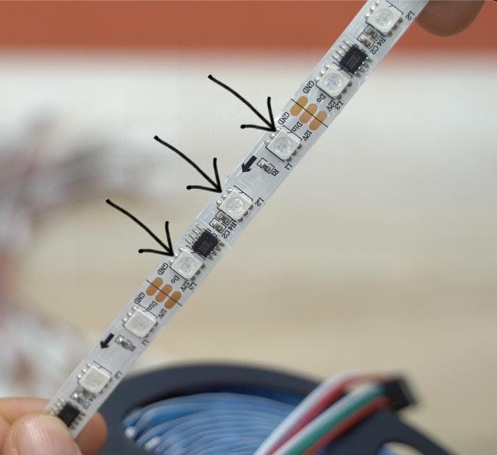
Once you have cut as many of these as you have triangles (14 in my case) you can then attach an LED connector wire to each of the incoming sides of the LED strips. You can work out the incoming side as the arrows showing the direction of data transfer through the strips is pointing away from it.
When adding the LED connector don't forget to also ensure that the red wire on the connector is connecting to the 12v pad on the LED strip. If we confuse our power wires during this project we are likely to damage something later when we apply power to the project.
Step 7: Fitting to Inside Triangular Panels
1 / 5
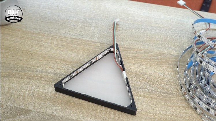
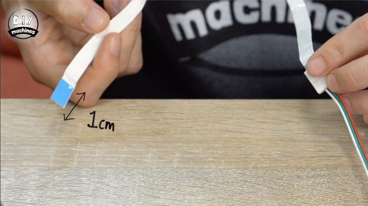
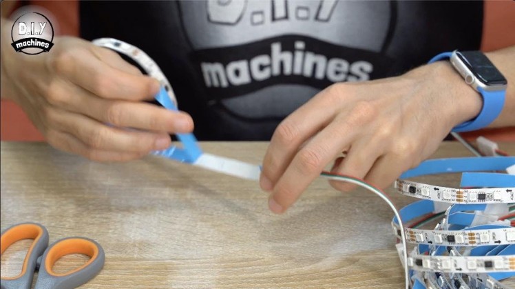
Before we fit this into the inside of our triangular panels you should remove all but the last 1cm of self adhesive backing from the rear of the strips. Having the last 1cm of backing on the unconnected end will make it much easier to slide the LED connector onto this end later on in the build.
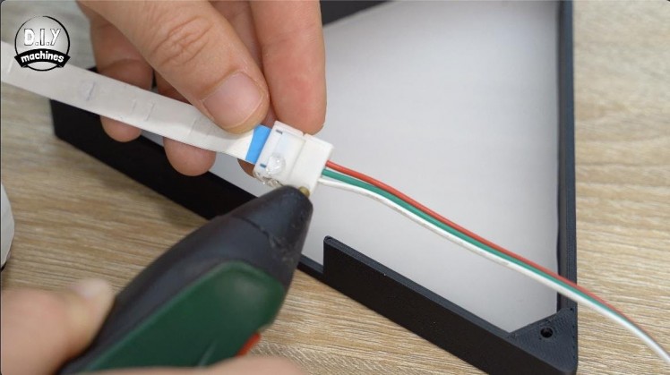
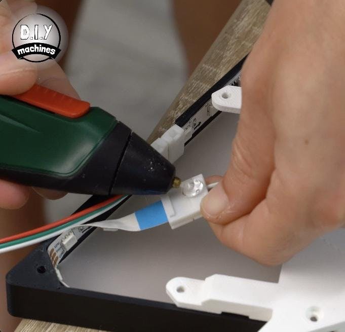
Add some glue to the connector and then position on the inside of the cutout in the triangle's walls. It should be positioned so that the red wire on the connector is on the top side which will result in the LEDs heading away to the left in a clock wise direction. Start pressing the LEDs firmly into place around the interior whilst keeping them as close to the top edge as possible. This will help to improve the diffusion of the LEDs later.
Complete this process to combine each LED strip with a triangle panel.
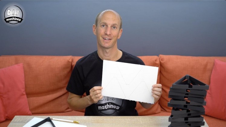
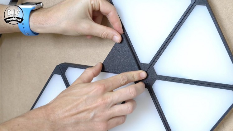
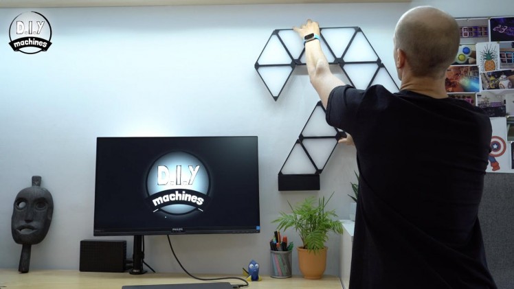
Step 8: Laying Out the Design
This is one of the fun but tricky stages - deciding how you want to lay out your Geoleaf panels.
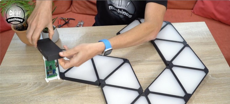
Start with your first triangle where you will intend to connect the power and control electronics later. (The control electronics is housed in the small grey rectangle I showed you earlier in the intro of the video). From this starting point, keep positioning each additional triangles connector up against a side of the previous triangle a create your layout.
Don't forget that we are currently looking at the project from the rear so once it has been hung on the wall it's shape will have flipped left to right. :)
Step 9: Preparing the Bases
1 / 13
For this step you will need:
- M3x8 bolts
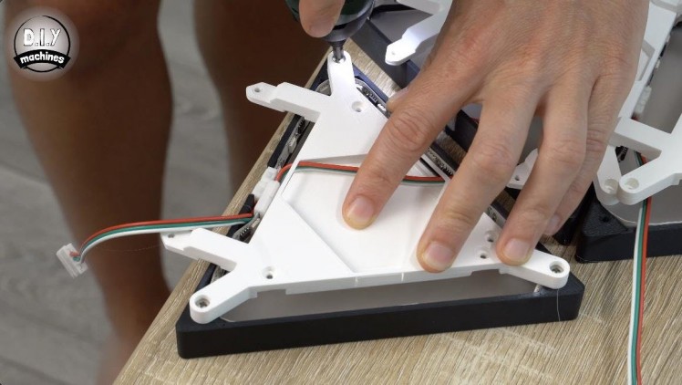
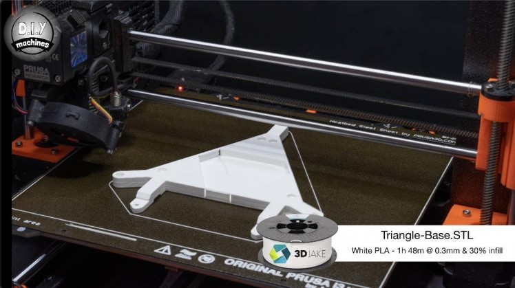
We then need to print the bases for the triangles, one for each triangle.
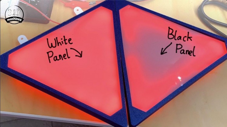
I highly recommend printing this in white filament as it has a big impact on the diffusion effect (take a look at the second photo attached which shows the difference between using a black and white back panel).
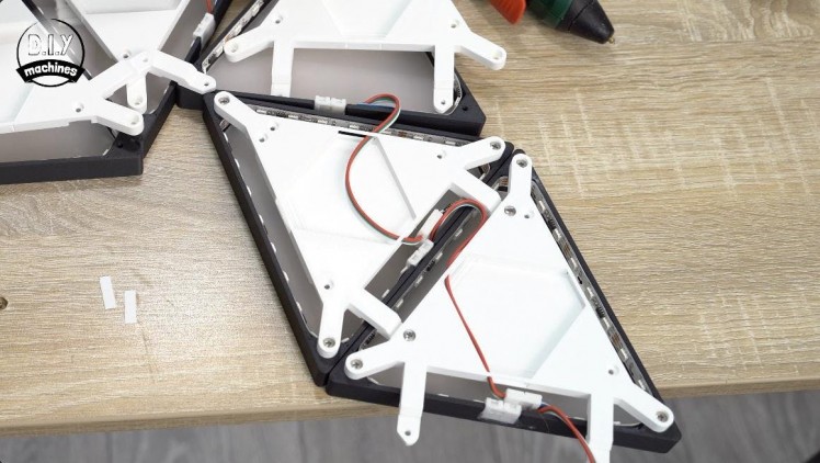
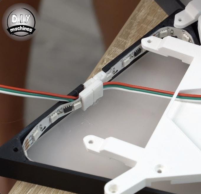
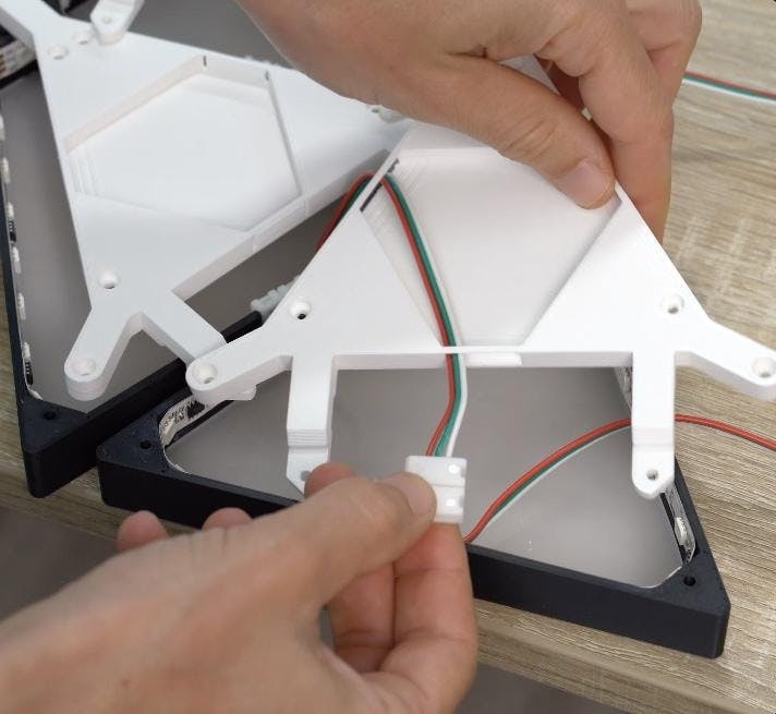
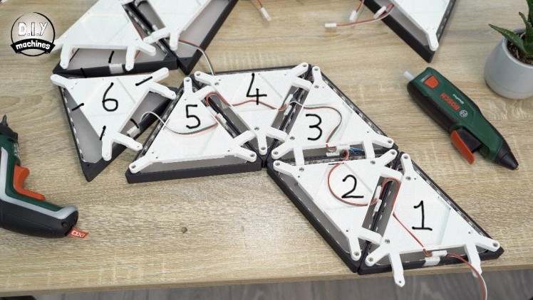
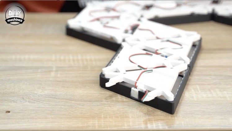
These are then temporarily laid out along the project so that the two legs on each print are pointing towards the same side as each of the triangles respective wire connectors. Go along the line of back panels and remove the pop-out walls on the print for the two sides of the triangle which adjoin another triangle.
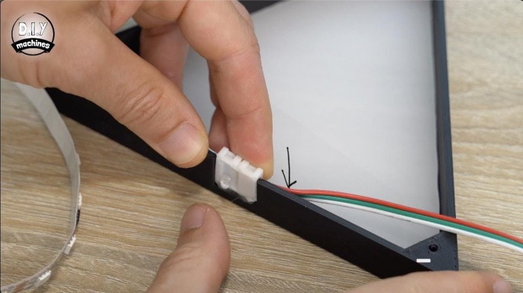
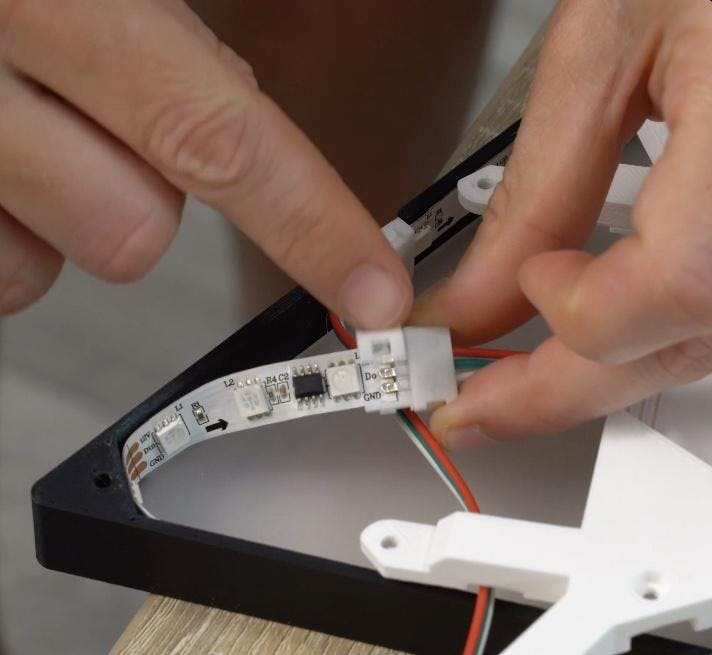
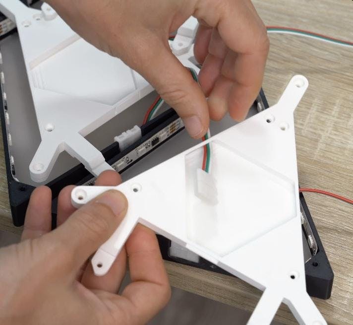
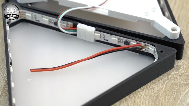
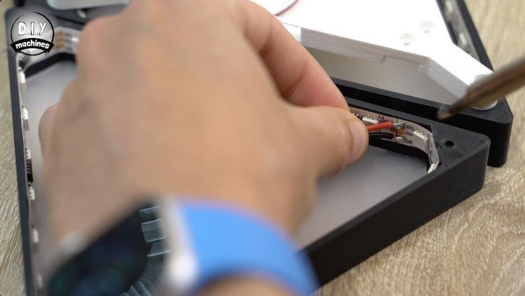
Starting from the first triangle, take the LED connector from the next triangle and pass it though the triangles holes we just popped the panels out of. Connect the connector to the unconnected end of the LEDs in this triangle and then use a dab of glue to hold the connector in place over the top of the existing one (check the photo's - it is a little difficult to describe in words).
Keep the connector up away from the acrylic to minimise any shadows it might cause showing on the other side of the acrylic.
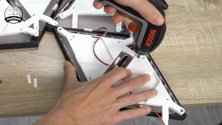
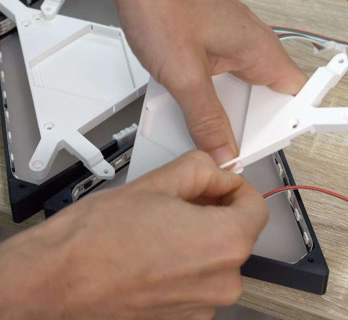
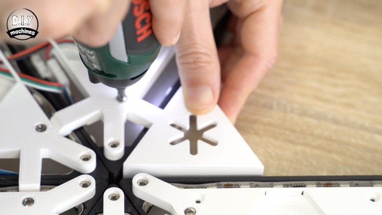
Use three M3x8 bolts to attach this panel to the triangle in the three corners. Repeat this for the first five triangles but additionally use two more bolts to attach the legs of the triangle to the previous one. This is how the shape is formed.
We need to do something a little different to every 6th panel, I'll explain more in the next step.
Step 10: Voltage Boosting
1 / 5
For this step you will need:
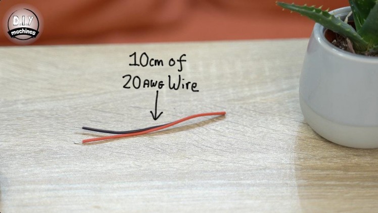
- 10cm lengths of 20AWG wire
- Soldering iron
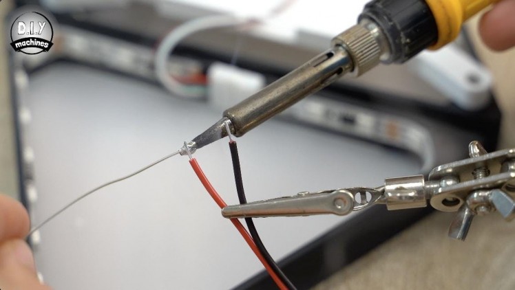
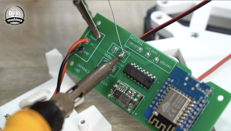
After every five panels we need to add a couple of 10cm long wires to a 12v and GND point on the next LED strip so that we can inject a boost of 12v power later. This is because the wiring in the LED strip is thin and we suffer what’s called ‘Voltage Drop’ the further we go along the wire. This will show itself as dimming LEDs that also appear to be tinted brown.
Solder two 10cm long wires to the first 12v and ground pads just along from the connector o this 6th panel.
We will connect these two wires to the rest of the project later - for now they can be disregarded and we can carry on fitting the back panel for this light and the next five before attaching another couple of wires to the 12th panel.
Keep repeating this pattern until every panel has a back plate.
Step 11: Prepare the Mini360 DC-DC Converter
1 / 3
For this step you will need:
- Mini360 DC-DC buck converter
- Small screwdriver
- Multimeter
- 12v power supply
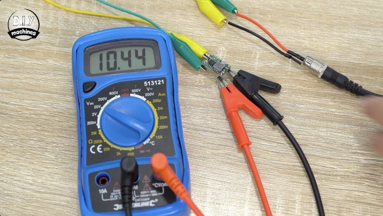
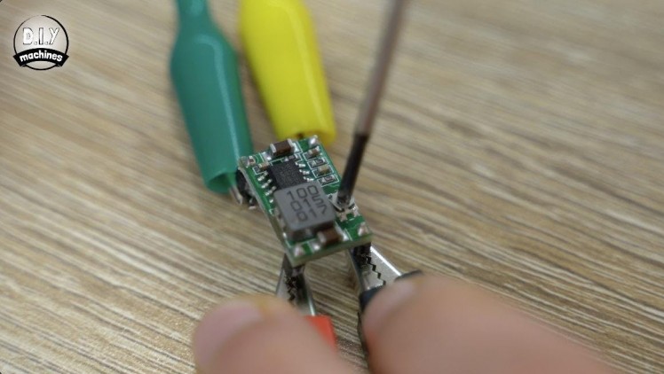
Before we can connect the Mini360 to the rest of our circuit later we need to configure it's output voltage. The Mini360 can be set to output between 1v to 17v - we need it to output a teeny tiny smidge over 5v.
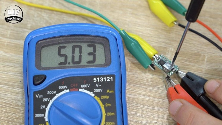
To do this we can temporarily hook up its two inputs (check the underside of the board) to our 12v power supply which we will be using for the project, and to its two outputs we need to connect a multimeter.
Set the multimeter to measure a voltage up to 20v and switch on the power supply. You can then use a small screwdriver to turn the potentiometer whilst watching the output. Aim for something between 5v and 5.05v.
Once you have done this it can be disconnected and put to one side for use later.
Step 12: Prepare the ESP3266 (Wemos D1 Mini)
1 / 2

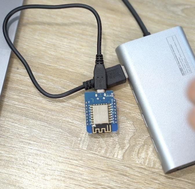
The ESP8266 is next, connect it to your computer using a USB cable and then navigate to https://install.wled.me/ using the chrome web browser.
Press ‘Install’ and then choose your board. Once completed we can then disconnect this and set it aside for now as well. Easy huh? :)
Step 13: Printing the Control Panel Housing
1 / 3

We need a couple more prints for the electronics. The control base and control cover.
I printed both of mine with colours and materials that match the rest of the project - white and matt black.
Step 14: The PCB / Perforated Board Options
1 / 4
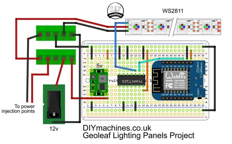
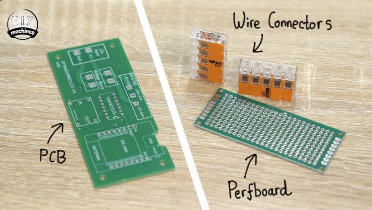
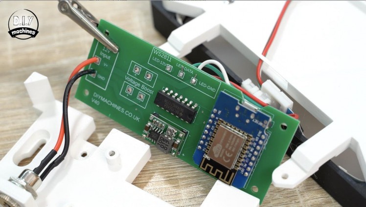
There are two methods for connecting the electronics together for this project, as mentioned at the beginning. This is either using the PCB which I designed for this project or using something like an Adafruit Perma-proto to connect the electronics and some wago connectors for the higher amperage circuits.
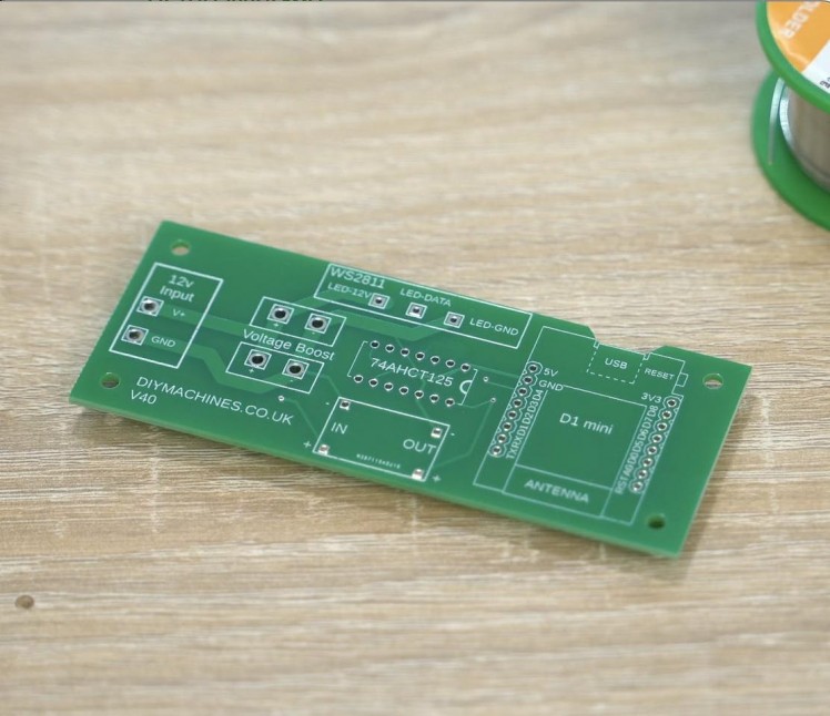
I really recommend the PCB method - not just because I'm proud of my very new but growing PCB skills, but because it comes with labels and outlines for all of the components and requires significantly less soldering.
To order a PCB you can go to PCBWays website where there is a page for this project: https://geni.us/GeoLeafPCB here you can order 5 copies of the PCB delivered for only about $8 / £7 if you choose the slower shipping times. All the settings and configuration for the PCB order have been pre-filled, you only need to add it to your basket and proceed with payment.
The rest of this tutorial will explain how to proceed with the PCB, however, if you would rather use a Perma-proto board and wire connectors then I have drawn out the wiring diagram which you can find above.
Step 15: Assembling the PCB - Components
1 / 4

For this step you will need:
- PCB
- ESP8266 (that we flashed with WLED earlier)
- Logic Level Converter (LLC)
- Mini360 (which we set to output 5v earlier)
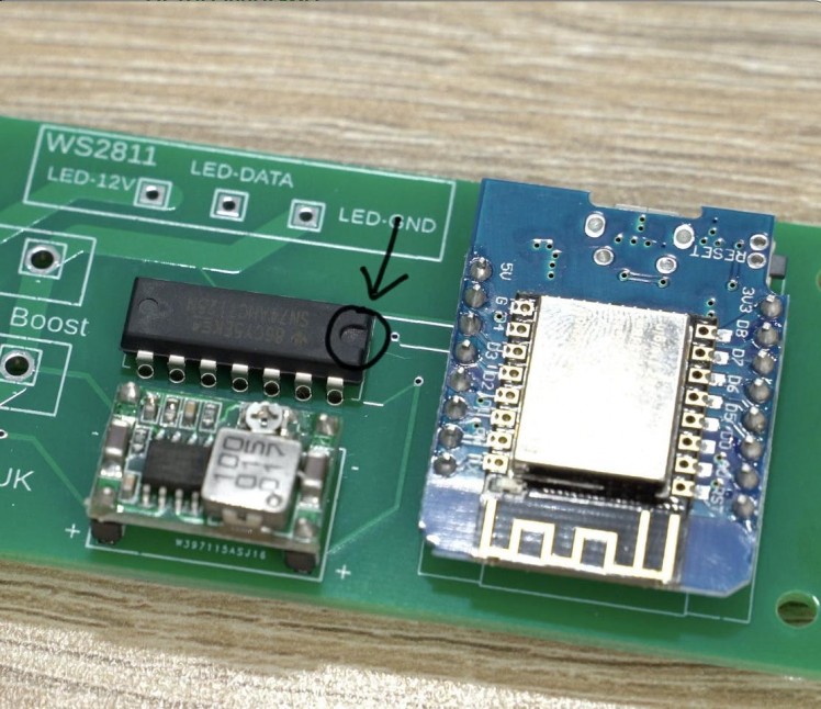
Once you have your PCB we can add the three main components by inserting their legs though their respective holes for their location on the PCB.
You need to ensure that the components are inserted in the correct orientation:
- The ESP8266 should have its USB port facing upwards as indicated in its outline on the board.
- The Mini360 has positive and negative labels for both the input and output on the underside of it's board. This should be matched with its outline.
- The logic level shifter has a small semi circle indent at one end, which should be on the same side as the ESP8266 as indicated by the markings for its outline.
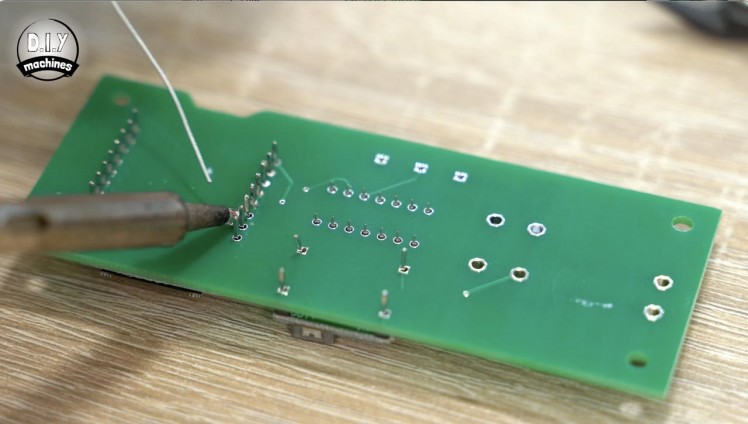
After you have checked the components are oriented correctly the board can be turned over and soldered from the other side.
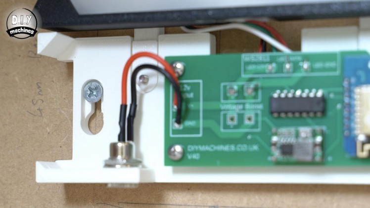
Step 16: Assembling the PCB - Power
1 / 5

For this step you will need:
- PCB Assembly
- 5A (or greater) DC Barrel
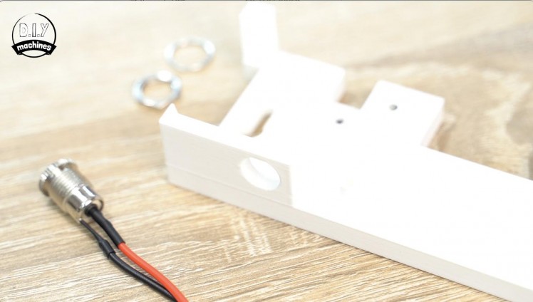
- Control Base (3D Printed)
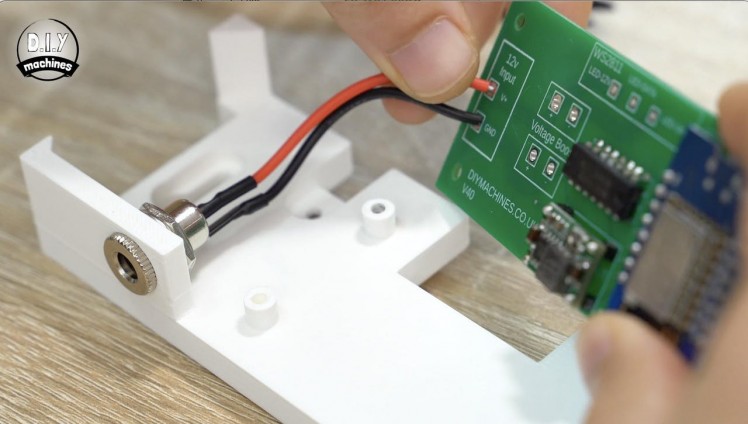
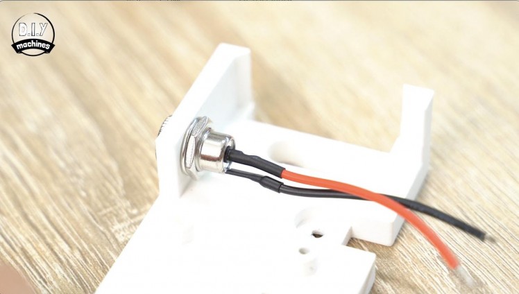
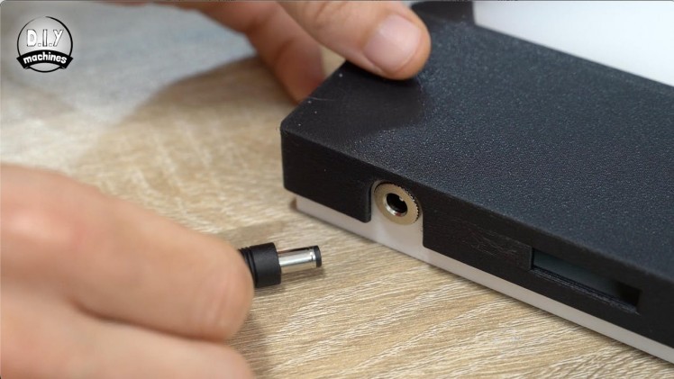
The female barrel connector for our power supply is added into the 3D printed housing from the outside of the print and then secured with the included washer and nut.
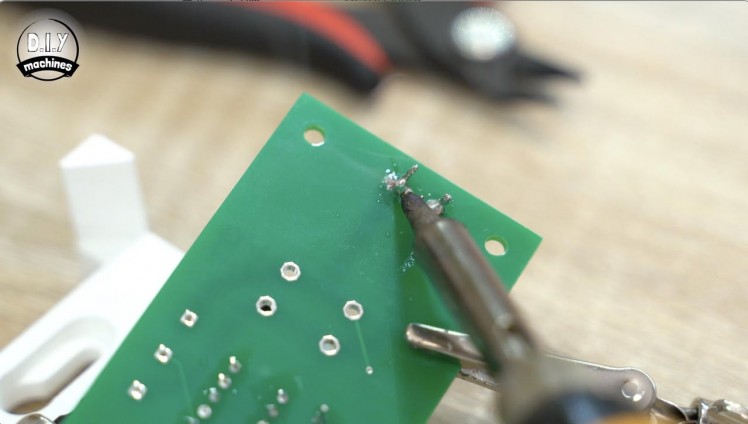
Its two leads are soldered to the respective positive and negative terminal on the far left of the PCB labelled as '12v Input'. If the leads on your connector are rather long then you might want to consider reducing their length before soldering them into place.
To see if they are too long you can temporarily hold the PCB over the four stand offs in the 3D print to see just how far it needs to reach.
Step 17: Assembling the PCB - LEDs
1 / 6
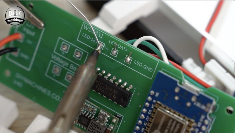
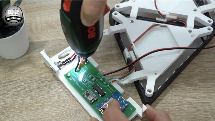
Before we connect the first illuminated triangles LED connector to the PCB it should be trimmed down to about 5cm in length, removing the connector. We can then separate and strip the wires before soldering them to the PCB.
These wires are best inserted from the rear of the PCB and soldered on the front side. They are to be connected as follows:
- Red wire -> 'LED-12V'
- Green wire -> 'LED-DATA'
- White wire -> 'LED-GND'
Step 18: Assembling the PCB - Power Boosting
1 / 11
For this step you will need:
- Length of 20AWG wire
- Dual T-splice wire connectors
- M3x8 bolts (x6)
We will turn our attention back to the pairs of unconnected wires now which we added to every 6th panel along the length of project earlier to help us inject 12v of power.
Cut a length of your twin core wire about 10% longer than the farthest wires which needs connecting as measured along the path of the triangular panels. We will trim any excess later.
Solder one end to the power boost pads on the main PCB passing them through the board from the rear (just like the LED wires) and soldering it on the frontside.
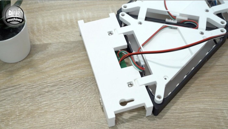
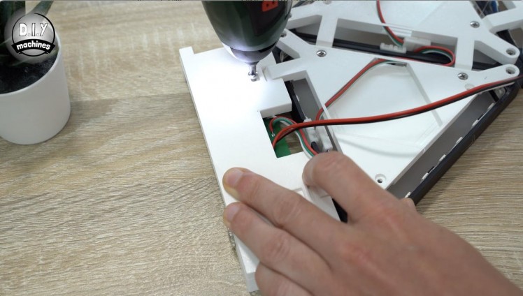
Four M3x8mm bolts are used to secure our PCB on top of the integral 3D printed standoffs. The Control Base can then be carefully turned over and attached to the bottom two feet of the first triangular panel using two more bolts.
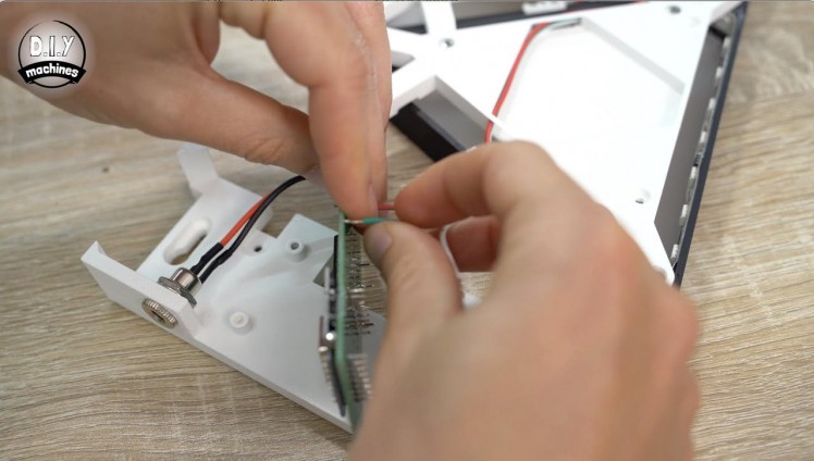
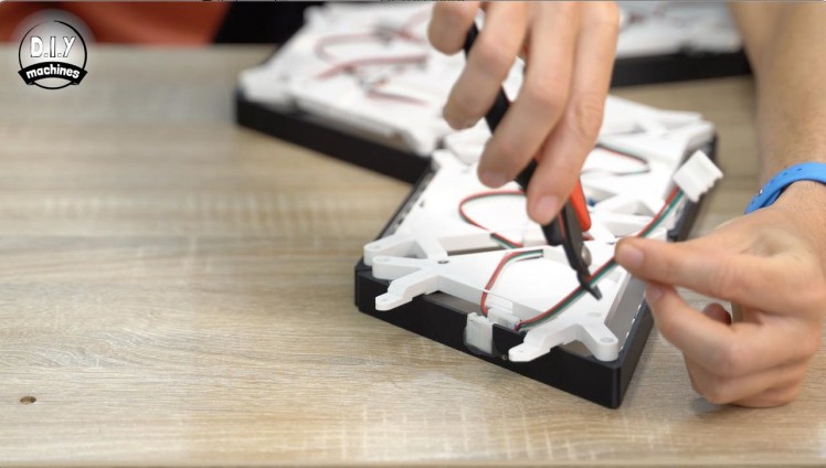
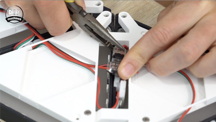
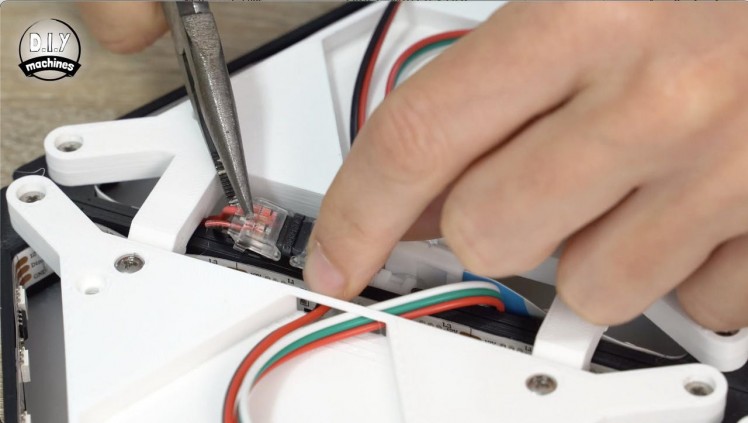
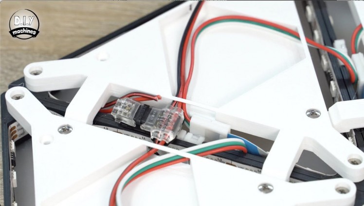
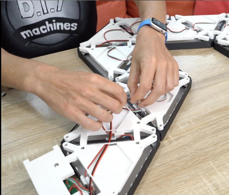
The new length of wire we attached to the PCB can then be threaded through the length of the project using the same path as the LED wire connectors. When you reach the point where we added two additional wires to the 6th panel you can use one of the T-splices to connect the two power wires to the LEDs.
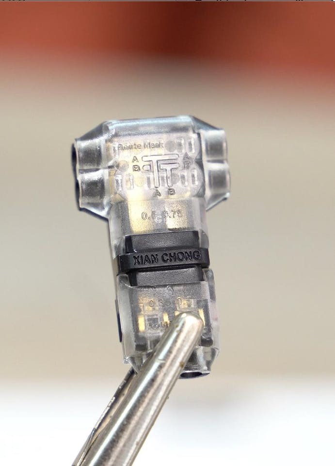
Take a good look at your connector to ensure that the correct wire is connecting to the correct lead on the LED. The wiring of your connector may be different to mine. The ones I'm using have a small diagram imprinted on the casing which shows how they are to be used.
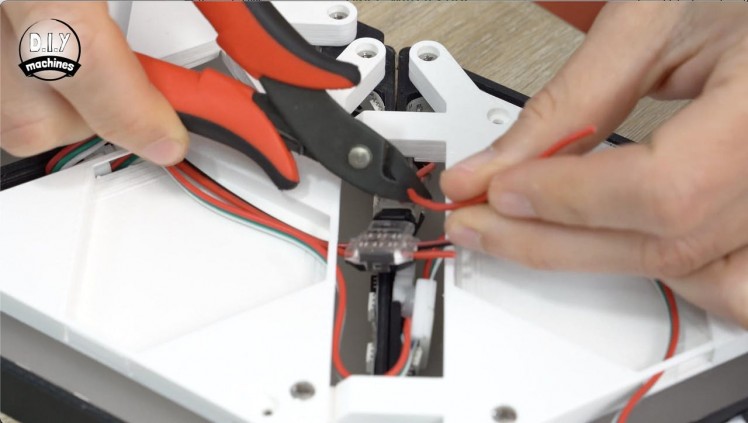
Do this by first clamping the connector to the long wire we're threading through. Then you can nestle the connector down between the two triangles. The wires we soldered to the LED strip earlier were purposely oversized so we first need to trim them to a more appropriate length. They can then be inserted into the end of the connector and clamped into place.
Resume passing the long wire through the projects length again until you reach the next pair of wire attached to the 12th illuminated panel. Repeat the same process to attach it to the LEDs power injection wires. If this is your last such boosting point, you can trim of the remainder of the wire.
Step 19: Adding the Lid
1 / 2
The project can then be flipped over so we can see the much smarter front side. The lid for the control panel is then slid on over the top with friction holding it snuggly into place.
That's all of the electronics wiring complete! Nice one. :)
Step 20: WLED - Getting Connected
1 / 5

Connect your 12v power supply to the barrel connector at the bottom of the project and switch on the power. All going well, you should see the first three or four triangles spring into life.
If you do not see this, disconnect the power and check your work done so far before progressing.
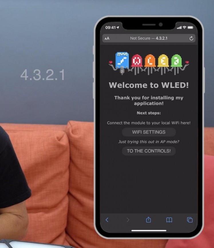
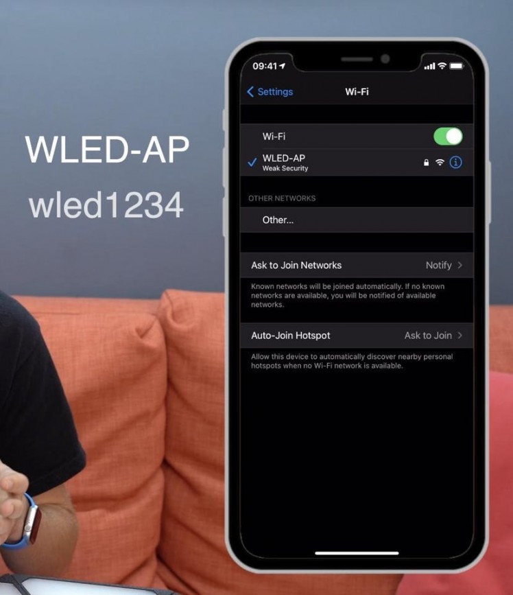
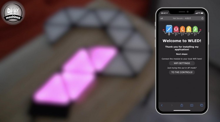
The easiest way to connect your smartphone or tablet is to scan the QR code in the photos above. This should connect you to the projects own wifi access point and present the first set-up screen.
If this does not work for you, or you would like to connect to the projects AP in a more traditional method then scan for the wi-fi network 'WLED-AP' and connect to it using the password 'wled1234'.
Once connected you can navigate to 4.3.2.1 in your devices web browser.
We can then proceed with the setup...
Step 21: WLED - Software Configuration
1 / 9

At this moment we have only a direct wi-fi connection to our project so we will configure it to connect to you main wi-fi network next. This is so that we can control it locally and using other services such as Alexa and Phillips Hue.
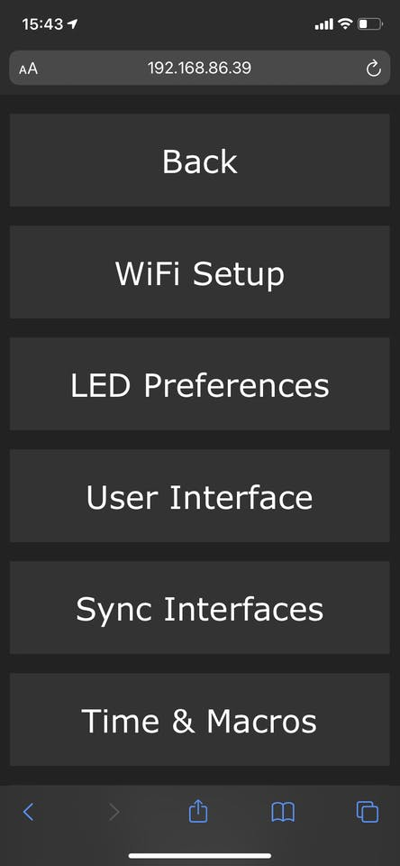
- Click ‘WIFI Settings’
- Enter name and password for your own wifi network in the top two boxes.
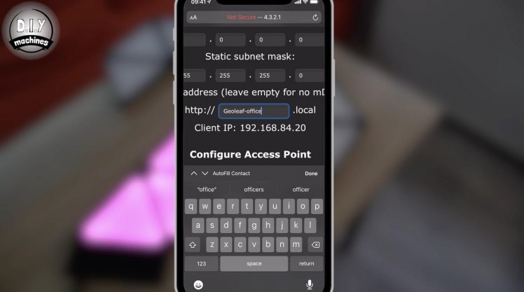
(Optionally you can also enter a mDNS address for accessing the configuration pages later instead of an having to use an IP address. I chose to call mine 'Geoleaf-Office'.)
- Once done, scroll to the bottom and press 'Save & Connect'.
The Wemos D1 Mini will now reboot which will only take a few seconds. Whilst this is happening you can now reconnect your phone to the same wifi network you connected the Geoleaf project to and navigate to the mDNS address you just chose, or the projects IP address.
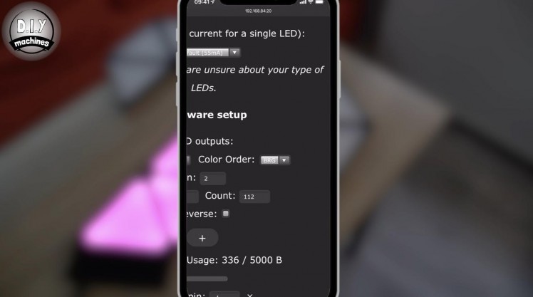
We now need to tell our project some more information about the LEDs we have connected to it.
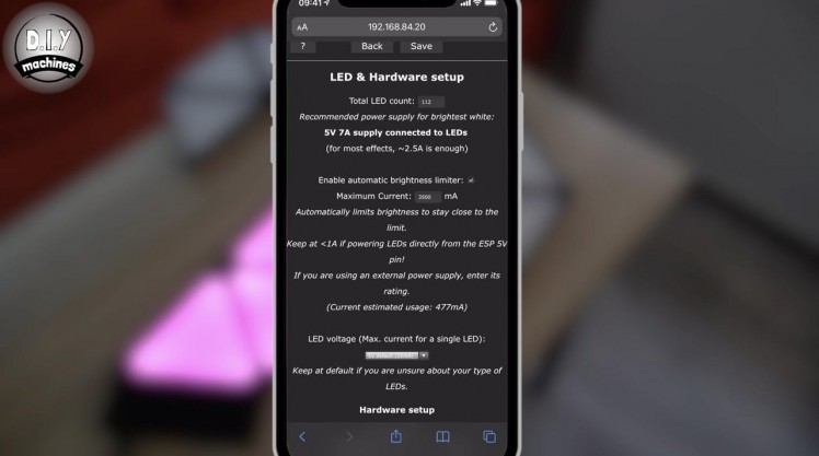
Once you have reconnected to the projects control page open the configuration page again but this time navigate to the 'LED Preferences'. On this page scroll down and update the 'LED count'. This should be the number of triangles you are using in the project x8. So for my 14 panels I will enter 112. (14x8).
You need to also set the maximum current to 3500 ma. This is important to keep the current within the capabilities of the project as I have shown you how to build it. It will only try to automatically and intelligently limit the maximum brightness of the LED's depending on how many are on at any moment and what colour they are showing (some colours require more energy than others to shine).
Finally under 'hardware setup' change the 'colour order' to BRG. (Blue Red Green).
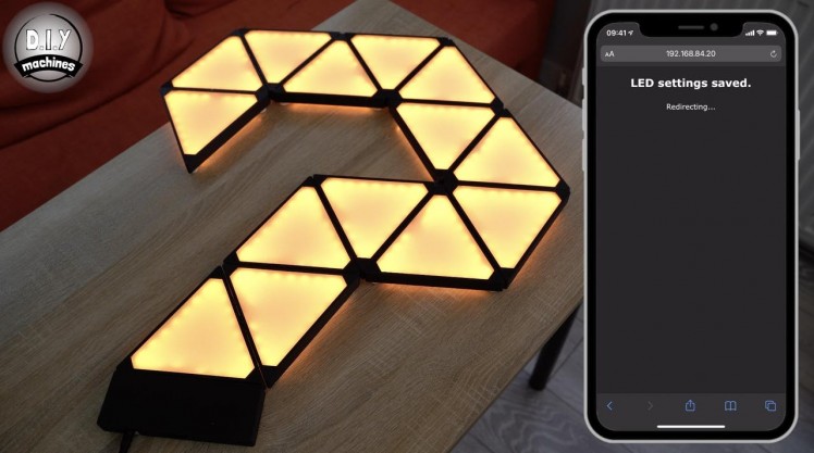
We can verify the settings by heading back to the main page and cycling through the red, green and blue colours.
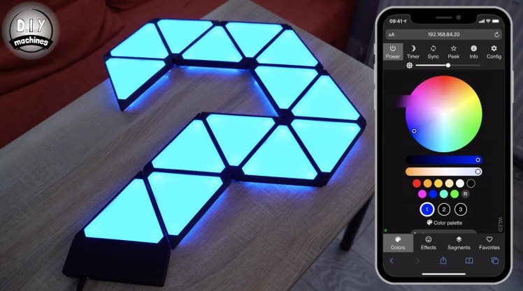
Step 22: WLED - Using the Controls
1 / 7
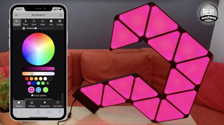
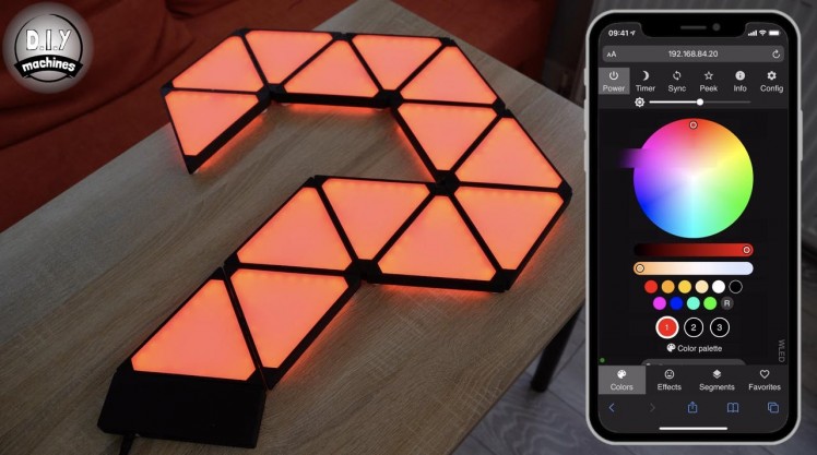
There are absolutely loads of good quality guides on the internet for using WLED so I will not go into great detail here. But I won't leave you without a quick crash course in the basics.
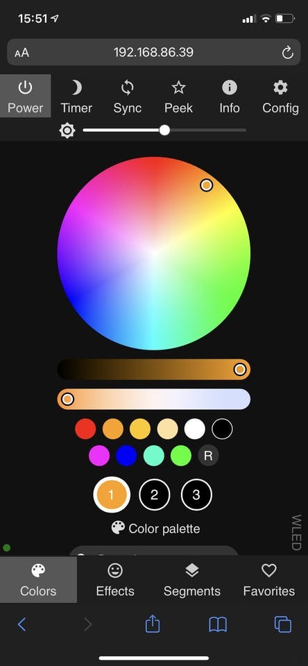
On the main screen is a brightness slider found at the top of the screen. This is the master brightness control and can be accessed from any screen.
There are four main pages which can be accessed from the four main tabs at the bottom of the screen; Colours, Effects, Segments, Favourites. The first tab you find yourself on is the Colours tab.
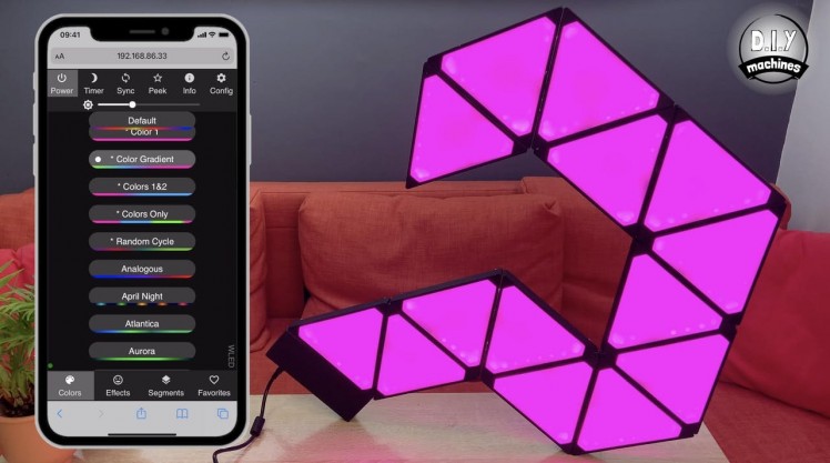
Colours Tab
WLED has a pallet of three main colours, accessed by the numbers 1,2,3 just below the colour pickers. Pressing one of these and then selecting a new colour from above will update it. At the moment the effect we have is known as 'Solid' and only uses the third colour. So for now the other colours chosen for colour one and two will not effect what your project will show, however, other effects can use more than one colour and will therefore allow you finer control.
If you scroll further down the colour tab there are pallets of pre-prepared colour schemes you can select from.
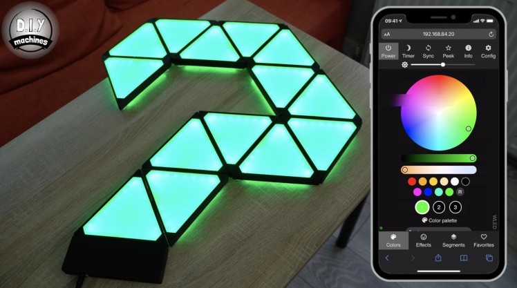
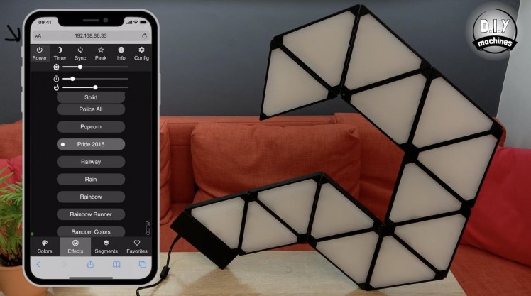
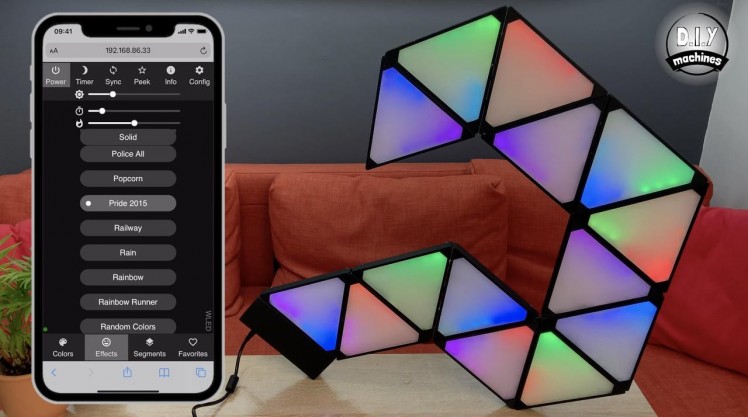
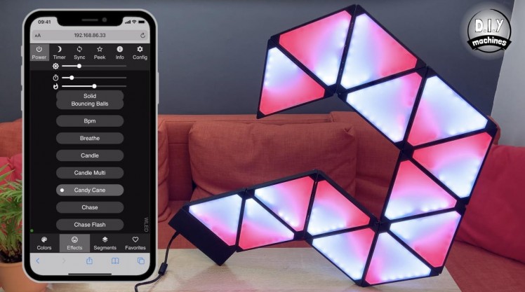
Effects Tab
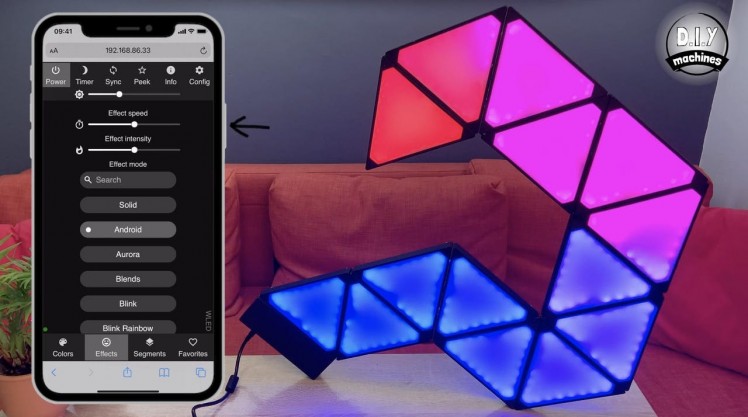
The Effects page allows you change between various dynamic and static animation for the LED panels.
This tab introduces an additional slider at the top of the page which controls the speed/tempo of the dynamic effects.
In a similar fashion to the colours tab, this page has a long list of predesigned lighting effects. There are plenty here to choose from and it may take you a few minutes to find some of your favourites.
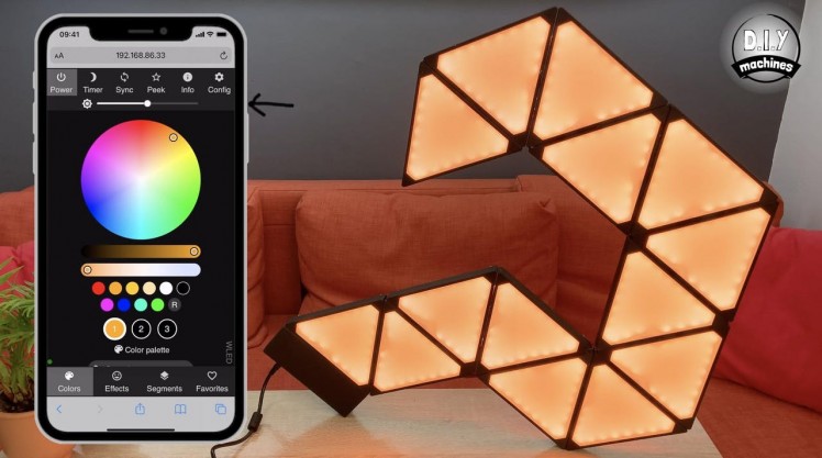
Power Control
At the very top left of the screen is the 'Power' button. This allows you to turn the LED's off and on easily from any screen. If you won't be using your panels for awhile I still recommend that you turn of the power supply at the wall connection.
Step 23: WLED - Alexa and Phillips Hue
1 / 14
The fantastic WLED software allows us to connect this project with Alexa and Philips Hue. If this is something that you're not interested in doing you can just skip past this step.
Integrating with Amazon Alexa
The Nanoleaf project can be integrated with Amazon's Alexa voice assistant service to allow you to control the colour, brightness and toggle the panels on and off with your voice. This option also allows you to further integrate it into other services such as IFTT's routines. It is very easy to add:
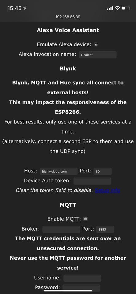
- On the main screen of WLED open the 'Config' screen (top right button) followed by the 'Sync Interfaces' menu.
- Scroll down until you reach the 'Alexa Voice Assistant' section. Check the box to enable 'Emulate Alexa Device' and then choose an easily spoken and heard 'Alexa invocation name:' You can then scroll to the bottom and save your changes.
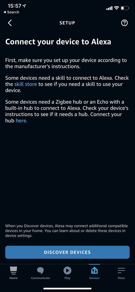
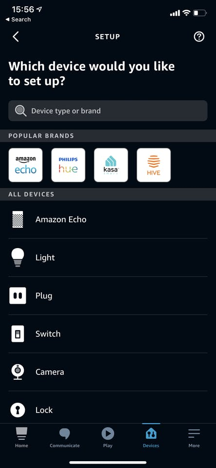
- Now open the Alexa app on your phone and click the '+' in the top right to begin adding a device.
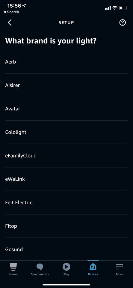
- Choose to add a light and then scroll to the bottom of the list of brands and choose 'Other'.
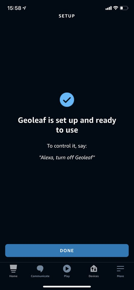
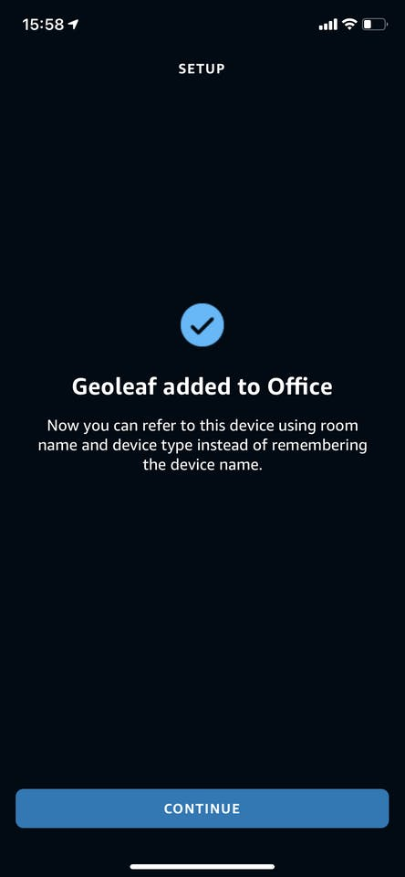
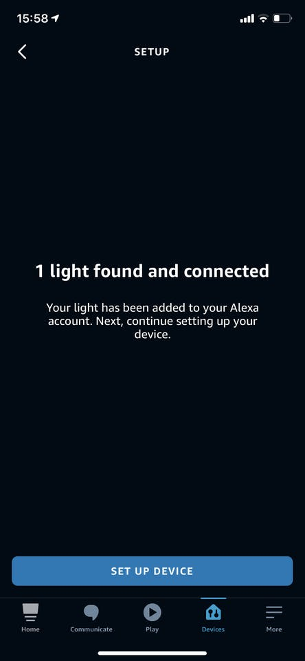
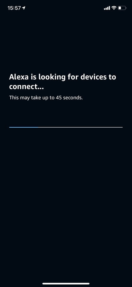
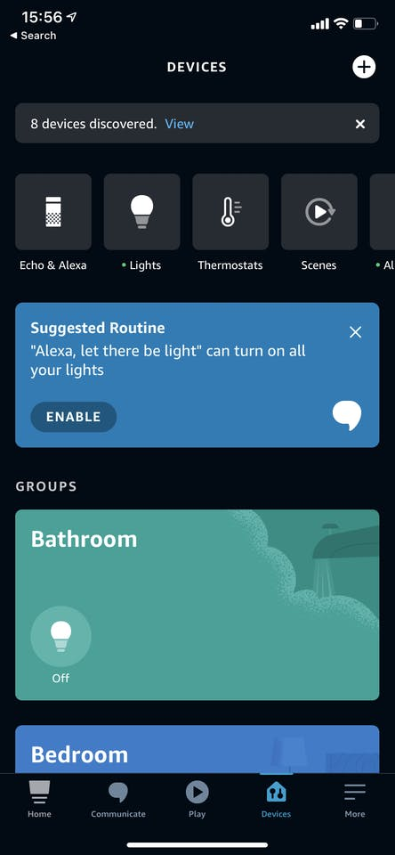
- Proceed to 'Discover Devices'. Alexa will start to search for new devices, keep your Geoleaf project powered on during this search.
- Once you have received confirmation that the project has been found Alexa will guide yo through setting it up and how to control it.
Integrating with Philips Hue
Integration with Philips Hue's smart lighting system is a little more involved than the Alexa integration shown above and in the photos. To integrate with Hue we will have the project poll the Hue Bridge regularly and ask it about the status of one of your existing lights. The Geoleaf project will then try to replicate the settings of this build as closely as it can. For example, my Geoleaf panels are in my office and I have it follow the brightness and colour of my ceiling light bulb. This way it switches on and off when I enter and leave my home office space.
Here is some documentation provided on the official Wiki for WLED: https://github.com/Aircoookie/WLED/wiki/Philips-hue-sync and here is some documentation from Philips Hue on interacting with your Hue bridge to find bulb IDs which you need to enter int the WLED app: https://developers.meethue.com/develop/get-started-2/ . Both of these resources might help you with this integration but here is a super concise run through of what is required:
In a web browser navigate to: https://<bridge ip address>/debug/clip.html (ensuring you substitute your IP address). This will open the 'CLIP API Debugger' of your Hue Bridge.To be able to ask for more sensitive information about your Hue system you need to ask for a username to prove who we are. Do this by entering the following into the fields of the API Debugger: URL =/apiMessage Body ={"devicetype":"my_hue_app#geoleaf"} This time enter the following information into the fields: URL =/api/YOUR-UNIQUE-USERNAME
- Find the IP address of your Hue bridge by either clicking here (if you're on the same network at the moment) or by opening the Hue app, go to the settings menu, go to Hue Bridges, select your bridge and note its IP address.
- And then press the 'POST' button. This should return an error saying 'link button not pressed'. This is a security step to ensure you should be allowed access to your Hue data. Press the physical button on top of your Hue Bridge and then press 'POST' again.
- This time it will generate unique username for you. Note this down - it will be a long string of letters and numbers.
- And press the 'GET' button. This will return all the information about your Hue system.
- This information can then be copied from the results and pasted into a JSON viewer such as http://jsonviewer.stack.hu. From here you can find the bulb you would like to mimic, take note of its ID and enter this into WLED.
Step 24: Wall Hanging
1 / 9
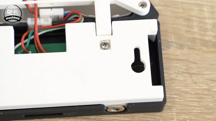
There are two different methods you can use to hang your Geoleaf project on the wall. You can either use the less destructive 3M command strips or the more permanent method with a screw and the mounting points provided in the project.
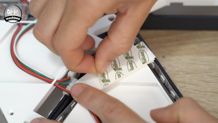
3M Command Strips
These are self adhesive pads. One side sticks to the wall and the other the project. A velcro like finish allows you to then join the two halves together. (Full instructions should be followed on the packet).
It's ideal if you don't want to (or can't) make holes in the wall for a screw. They are also designed to be easily removed later whist leaving no marks or residue. The medium and large sizes are more then strong enough to mount this project.
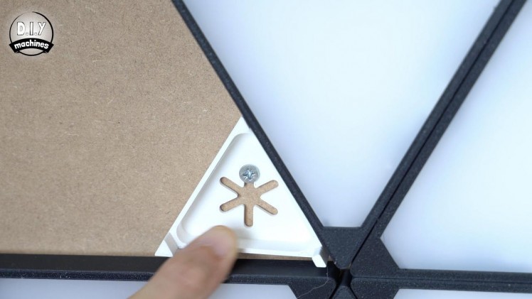
Mount with screws
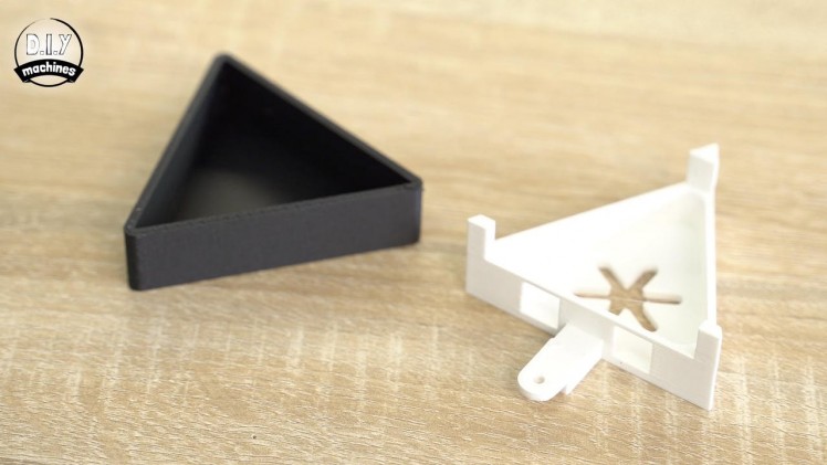
I also designed some 3D printable mini triangles (with matching lids) which provide mounting points for screws and nails. The mini triangles match the aesthetics of the larger illuminated panels whilst utilising the same interlocking system and an M3x8 bolt.
Mine were printed in matching PLA colours. You can add as many of these as you deem necessary. There is also an additional mounting point provided in the back panel of the rectangular control housing which you have already printed. :)
Step 25: Some Words of Warning...
I do need to provide a few warnings for this project, just to ensure that you don't cause any harm to yourself or property:
- Don't draw too much current: LEDs, particular when you are using a lot of them at bright settings, can draw a large amount of current. Because of this you must use the software limiter in WLED to cap the peak theoretical current draw.This will help to ensure that the wires do not get too hot or we damage the power supply.
- Add more panels responsibly: If you decide to add additional panels to your project, leave the software current limiter in place at its current value. This will only limit the brightness of the panels when required based on their calculated current draw based on how many LEDs are lit at any point and their respective colours.
- If you increase the power supply or demand, ensure you understand what you're doing: If you don't, please ask someone who will. An inappropriately specced power supply or wire thickness (including the PCB) may result in component failure and damage to you, your project or even other property.
Step 26: Project Completed!
Congratulations, that's the project completed! Time to sit back and enjoy the fruits of your labour. :)
I would love it if you wanted to support my projects, please consider subscribing to me on here and Youtube (https://www.youtube.com/diymachines). I also have a Patreon page where some very kind people are helping me to cover the cost of designing, documenting and sharing these projects. Please consider joining them in any way if you can.
Thanks for reading to the end, have a wonderful day and until next time. Ciao for now.
Schematics, diagrams and documents
CAD, enclosures and custom parts
Code
Credits
Related products


Leave your feedback...