
Fiber Optic Fault Alert With Blues, Edge Impulse & Qubitro

Made by pradeeplogu0 / Communication / Home Automation / Security / IoT
About the project
This project tutorial will show you how to implement a Fiber Optic Cable fault detection system with machine learning, Blues & Qubitro.
Project info
Difficulty: Moderate
Platforms: DFRobot, Edge Impulse
Estimated time: 1 hour
License: GNU General Public License, version 3 or later (GPL3+)
Items used in this project
Hardware components

Story
Introduction:
In telecommunications, fiber optic cables play a crucial role in transmitting data over long distances at high speeds. However, like any other technology, fiber optic cables are prone to faults and failures. This project tutorial will show you how to implement a Fiber Optic Cable fault detection system with machine learning and Blues.
What is a Fiber Optic Network Cable Fault Alert System?
A Fiber Optic Network Cable Fault Alert System is a specialized piece of equipment designed to monitor the health of fiber optic cables. It can detect faults in the cable and alert users in real time, allowing for quick identification and resolution of issues.
How Does It Work?
The device works by continuously monitoring the Fiber Media Converter’s led indicators. If there is a fault in the cable, such as a break or a bend that is too sharp, the LED indicators will indicate those issues. And by using the Machine Learning algorithm we can classify the issue.
The system can detect this disruption and will trigger an alert via Blues Notehub and Qubitro.
Benefits of Using a Fiber Optic Network Cable Fault Alert System:
- Quick Fault Detection: The device can detect faults in real time, allowing for quick action to be taken to resolve the issue.
- Prevent Data Loss: By alerting users to faults quickly, the device can help prevent data loss that could occur if the fault goes unnoticed.
- Reduce Downtime: Quick fault detection and resolution can help reduce downtime, ensuring that the network remains up and running.
- Cost-Effective: By preventing data loss and reducing downtime, the device can save businesses a significant amount of money in the long run.
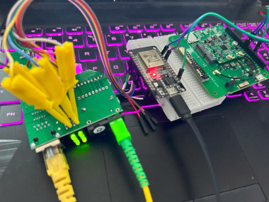
System Architecture:
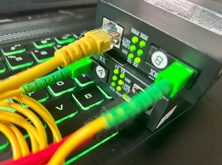
In this project, we’ll utilize a Fiber Optic Media Converter, a device capable of transforming Fiber Optic signals into Ethernet and vice versa. This converter has a series of LED indicators displaying RX, TX, and Network status.
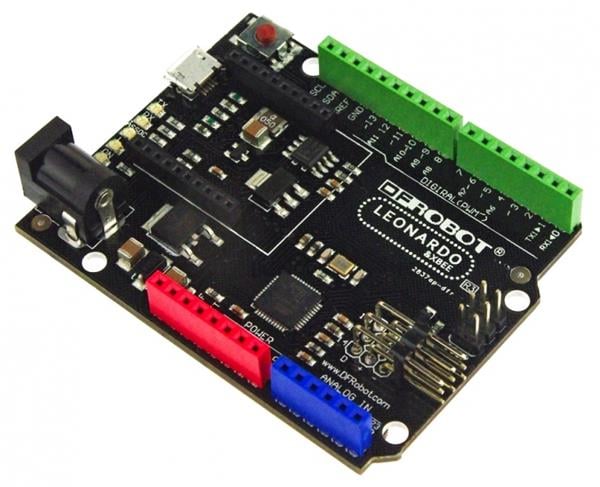
We’ll then employ an ESP32, connected to the Media Converter via jumper hooks. The ESP32 will enable us to keep track of the LED indicators. With the help of Edge Impulse, we can classify the patterns displayed by these LEDs.

Finally, by incorporating Blues Notecard, we can observe the status in real-time. We’ll use Qubitro to store this data and activate alerts as needed. This setup ensures efficient monitoring and prompt response to any changes in the system.
Hardware Implementation:
First, connect the jumper hooks to the Media Convert’s LED indicators and connect another end to the ESP32’s analog input pins.
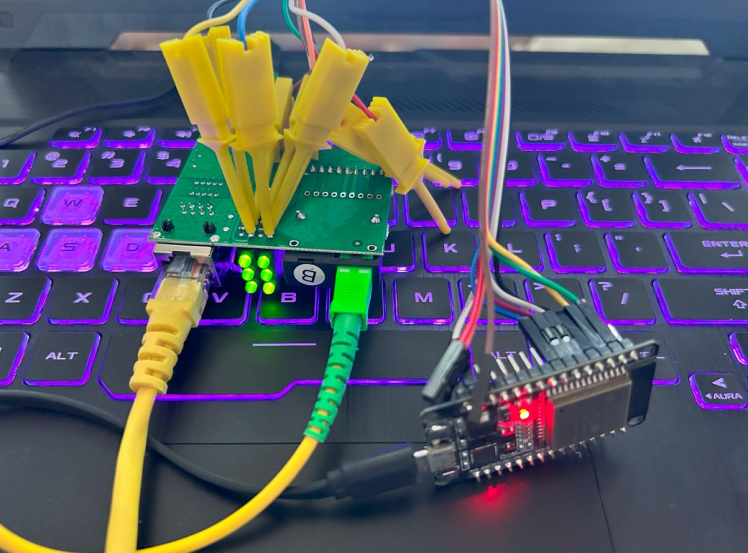
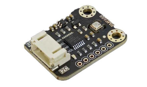
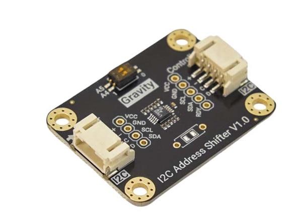
Next, connect the Blues Notecarrier via the I2C port to the ESP32 board.

EI Model Development:
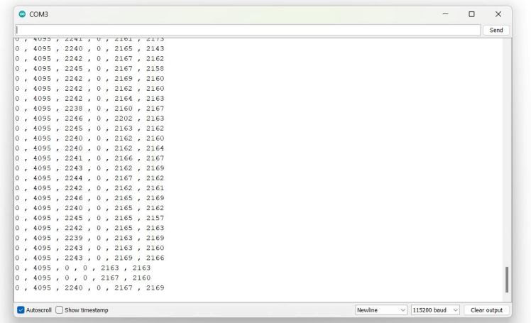
To create an Edge Impulse model. First, we need to collect the data samples from the Media Converter. Here is the simple Arduino Sketch that can collect the LED indicators data and print it in the serial terminal.
const int potPin = 36;
const int potPin1 = 39;
const int potPin2 = 34;
const int potPin3 = 35;
const int potPin4 = 32;
const int potPin5 = 33;
int potValue = 0;
int potValue1 = 0;
int potValue2 = 0;
int potValue3 = 0;
int potValue4 = 0;
int potValue5 = 0;
void setup() {
Serial.begin(115200);
delay(1000);
}
void loop() {
potValue = analogRead(potPin);
Serial.print(potValue);
Serial.print(" , ");
potValue1 = analogRead(potPin1);
Serial.print(potValue1);
Serial.print(" , ");
potValue2 = analogRead(potPin2);
Serial.print(potValue2);
Serial.print(" , ");
potValue3 = analogRead(potPin3);
Serial.print(potValue3);
Serial.print(" , ");
potValue4 = analogRead(potPin4);
Serial.print(potValue4);
Serial.print(" , ");
potValue5 = analogRead(potPin5);
Serial.println(potValue5);
delay(500);
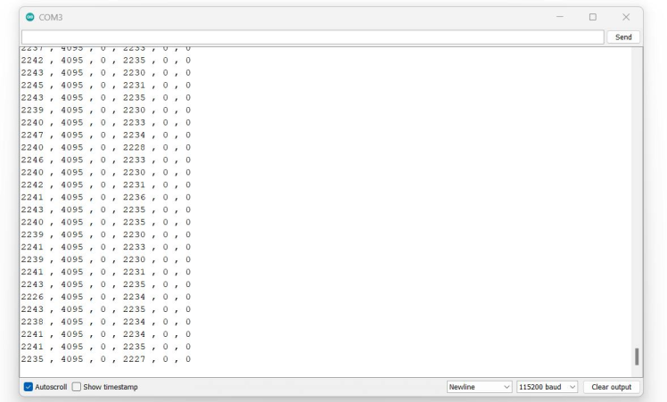
}Here is the serial monitor response.

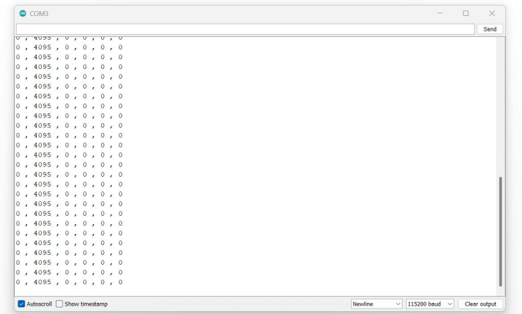
Let’s disconnect the optical cable and here is the serial monitor response.
Here is the serial terminal data when the ethernet port is disconnected.
And finally, here is the raw data when the system is down.
Next, we need to upload this data into the Edge Impulse. For that, I’m going to use the CSV data uploader in the Edge Impulse. Just copy the serial terminal data and paste it into the CSV file.
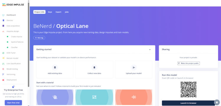
Creating an Edge Impulse Project:
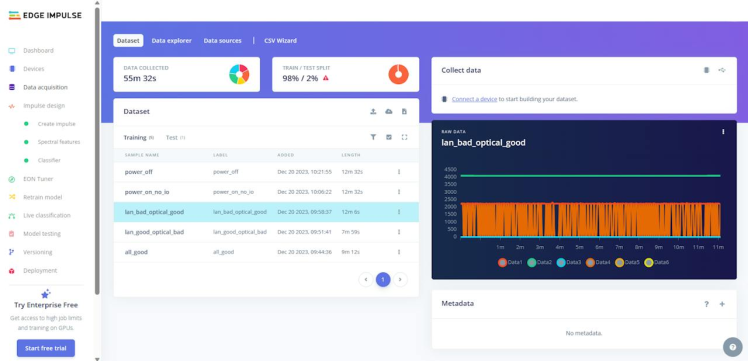
Next, create a new project on Edge Impulse. This is where you will import your CSV data and train your machine-learning model.
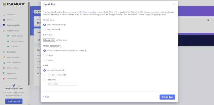
Importing CSV Data into Edge Impulse:
Edge Impulse provides a feature to import CSV data directly into your project. To do this, navigate to the ‘Data Acquisition’ tab in your project, and click on ‘Upload a file’. Here, you can upload your CSV file. Make sure to specify the correct labels for your data.
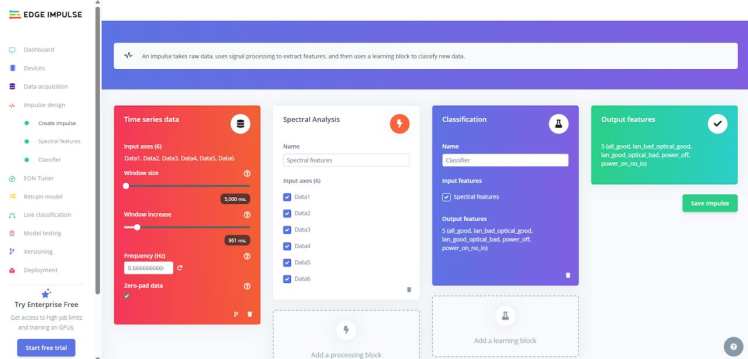
Designing Your Impulse:
After importing your data, you can start designing your impulse. An impulse is a sequence of signal-processing blocks and learning blocks that make up your machine-learning model. You can customize your impulse based on the requirements of your project.
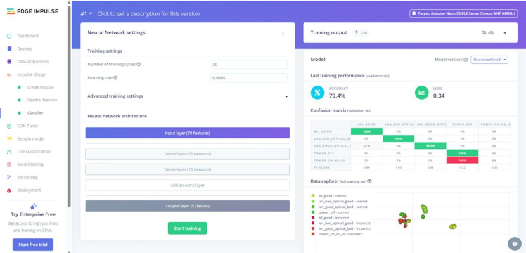
Training Your Model:
Once your impulse is set up, you can start training your model. Edge Impulse provides a user-friendly interface for this process. You can monitor the performance of your model in real-time, and make adjustments as necessary.
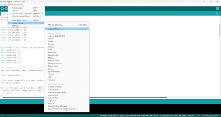
Model Testing:
Once downloaded the EL library we need to add that to our Arduino IDE.
Next, upload the following sketch to the ESP32 Board and look for the serial terminal response.
/* Edge Impulse ingestion SDK
Copyright (c) 2022 EdgeImpulse Inc.
Licensed under the Apache License, Version 2.0 (the "License");
you may not use this file except in compliance with the License.
You may obtain a copy of the License at
http://www.apache.org/licenses/LICENSE-2.0
Unless required by applicable law or agreed to in writing, software
distributed under the License is distributed on an "AS IS" BASIS,
WITHOUT WARRANTIES OR CONDITIONS OF ANY KIND, either express or implied.
See the License for the specific language governing permissions and
limitations under the License.
*/
// Potentiometer is connected to GPIO 34 (Analog ADC1_CH6)
const int potPin = 36;
const int potPin1 = 39;
const int potPin2 = 34;
const int potPin3 = 35;
const int potPin4 = 32;
const int potPin5 = 33;
// variable for storing the potentiometer value
int potValue = 0;
int potValue1 = 0;
int potValue2 = 0;
int potValue3 = 0;
int potValue4 = 0;
int potValue5 = 0;
/* Includes ---------------------------------------------------------------- */
#include <Optical_Lane_inferencing.h>
float features[18];
/**
@brief Copy raw feature data in out_ptr
Function called by inference library
@param[in] offset The offset
@param[in] length The length
@param out_ptr The out pointer
@return 0
*/
int raw_feature_get_data(size_t offset, size_t length, float *out_ptr) {
memcpy(out_ptr, features + offset, length * sizeof(float));
return 0;
}
void print_inference_result(ei_impulse_result_t result);
/**
@brief Arduino setup function
*/
void setup()
{
// put your setup code here, to run once:
Serial.begin(115200);
// comment out the below line to cancel the wait for USB connection (needed for native USB)
while (!Serial);
Serial.println("Edge Impulse Inferencing Demo");
}
/**
@brief Arduino main function
*/
void loop()
{
ei_printf("Edge Impulse standalone inferencing (Arduino)n");
features[0] = analogRead(potPin);
features[1] = analogRead(potPin1);
features[2] = analogRead(potPin2);
features[3] = analogRead(potPin3);
features[4] = analogRead(potPin4);
features[5] = analogRead(potPin5);
features[6] = analogRead(potPin);
features[7] = analogRead(potPin1);
features[8] = analogRead(potPin2);
features[9] = analogRead(potPin3);
features[10] = analogRead(potPin4);
features[11] = analogRead(potPin5);
features[12] = analogRead(potPin);
features[13] = analogRead(potPin1);
features[14] = analogRead(potPin2);
features[15] = analogRead(potPin3);
features[16] = analogRead(potPin4);
features[17] = analogRead(potPin5);
if (sizeof(features) / sizeof(float) != EI_CLASSIFIER_DSP_INPUT_FRAME_SIZE) {
ei_printf("The size of your 'features' array is not correct. Expected %lu items, but had %lun",
EI_CLASSIFIER_DSP_INPUT_FRAME_SIZE, sizeof(features) / sizeof(float));
delay(1000);
return;
}
ei_impulse_result_t result = { 0 };
// the features are stored into flash, and we don't want to load everything into RAM
signal_t features_signal;
features_signal.total_length = sizeof(features) / sizeof(features[0]);
features_signal.get_data = &raw_feature_get_data;
// invoke the impulse
EI_IMPULSE_ERROR res = run_classifier(&features_signal, &result, false /* debug */);
if (res != EI_IMPULSE_OK) {
ei_printf("ERR: Failed to run classifier (%d)n", res);
return;
}
// print inference return code
ei_printf("run_classifier returned: %drn", res);
print_inference_result(result);
delay(1000);
}
void print_inference_result(ei_impulse_result_t result) {
// Print how long it took to perform inference
ei_printf("Timing: DSP %d ms, inference %d ms, anomaly %d msrn",
result.timing.dsp,
result.timing.classification,
result.timing.anomaly);
// Print the prediction results (object detection)
#if EI_CLASSIFIER_OBJECT_DETECTION == 1
ei_printf("Object detection bounding boxes:rn");
for (uint32_t i = 0; i < result.bounding_boxes_count; i++) {
ei_impulse_result_bounding_box_t bb = result.bounding_boxes[i];
if (bb.value == 0) {
continue;
}
ei_printf(" %s (%f) [ x: %u, y: %u, width: %u, height: %u ]rn",
bb.label,
bb.value,
bb.x,
bb.y,
bb.width,
bb.height);
}
// Print the prediction results (classification)
#else
ei_printf("Predictions:rn");
for (uint16_t i = 0; i < EI_CLASSIFIER_LABEL_COUNT; i++) {
ei_printf(" %s: ", ei_classifier_inferencing_categories[i]);
ei_printf("%.5frn", result.classification[i].value);
}
#endif
// Print anomaly result (if it exists)
#if EI_CLASSIFIER_HAS_ANOMALY == 1
ei_printf("Anomaly prediction: %.3frn", result. Anomaly);
#endif
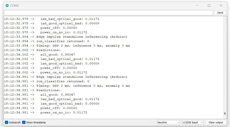
}Here is the serial port response in multiple scenarios.
Test 1: All _ Good
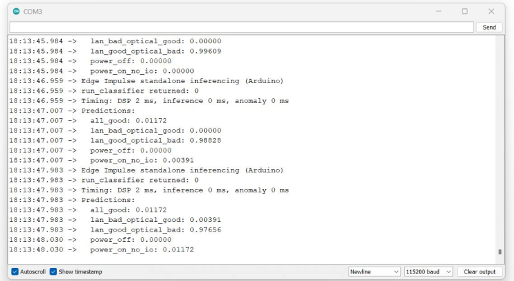
Test 2: Ethernet_Good_Optical_Fault.
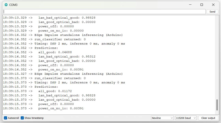
Test 3:Ethernet_Fault_Optical_Good.
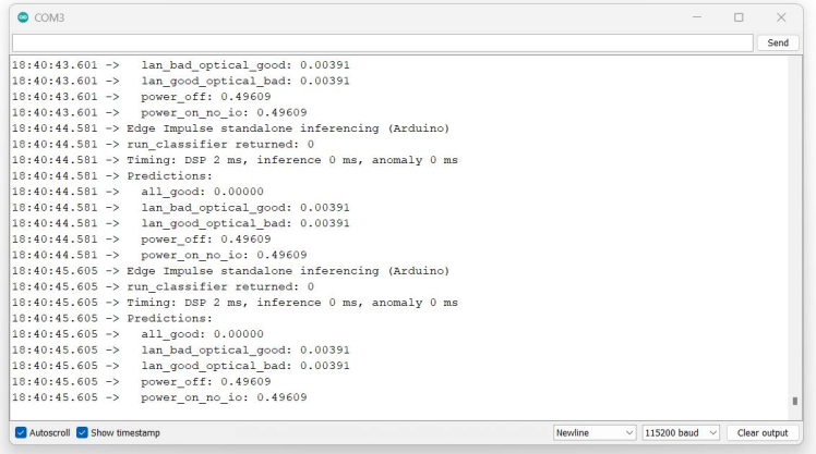
Test4: System_Down.
Blues Notecard Integration:
Now our system can detect network failures in different scenarios. Next, send our system status to the cloud networks via Blues Notecard. We have already connected the Notecard with the ESP32 via the I2C port. This part of the code will send the data when the system detects the failure.

Here is the Serial terminal response from the ESP32 board.

Now, we can see our system data in the Blues Notehubportal.
Once the data reaches Notehub, we will use Qubitroto visualize and make an alert function based on the received data.
Qubitro Integration:
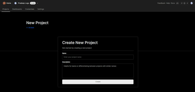
Navigate to the Qubitro Portaland to create a new project.
Then, select MQTT as the data source.
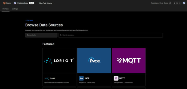
Next, enter all the input details as needed.

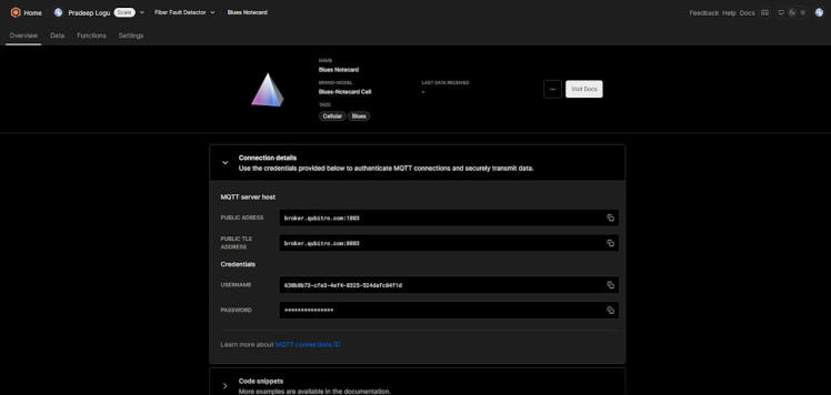
Then, open the created MQTT source and select the connection details. It will show you all the credentials. We need these credentials to transfer our data to Qubitro.
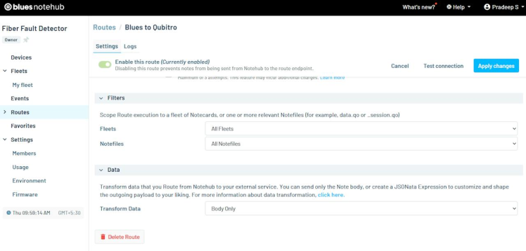
Let’s move on to the Blues Notehub’s route page. Here, we have to create a new MQTT route and change the username and password according to your Qubitro credentials.
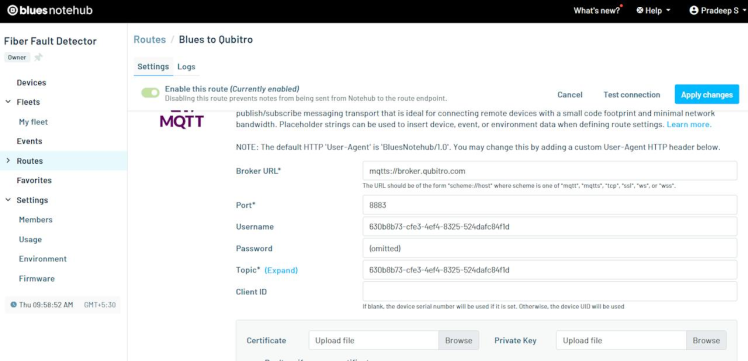
At the bottom, define which data should move to Qubitro.
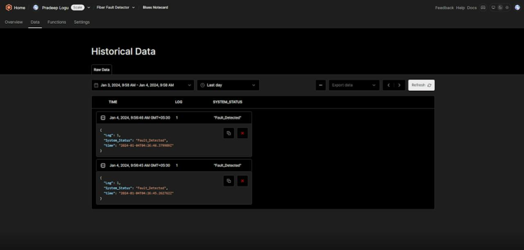
After the payload successfully transfers to Qubitro, open the Qubitro portal to monitor the incoming data.
Rule Engine Setup:
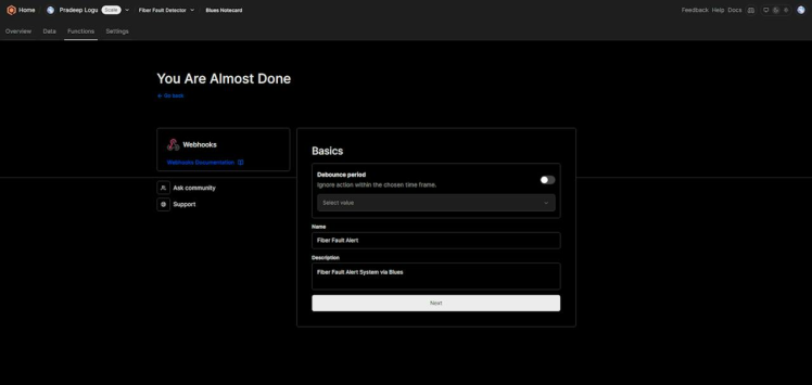
Next, navigate to the functions tab. In this function, we are going to build an alert system that can trigger the endpoint when the conditions are met.
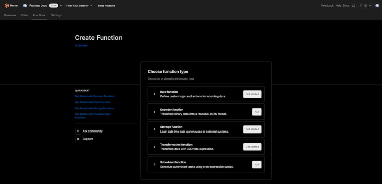
Select “Rule Function”, and choose the rule type.
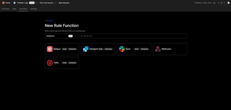
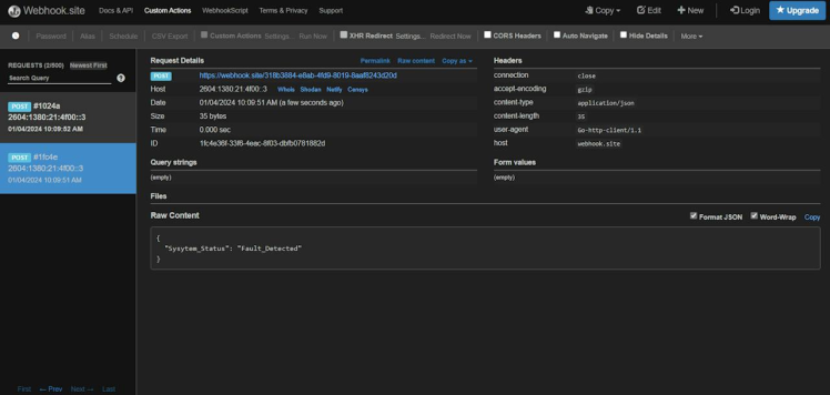
Here I used Webhooks. I entered all the basic details and moved to the next page.
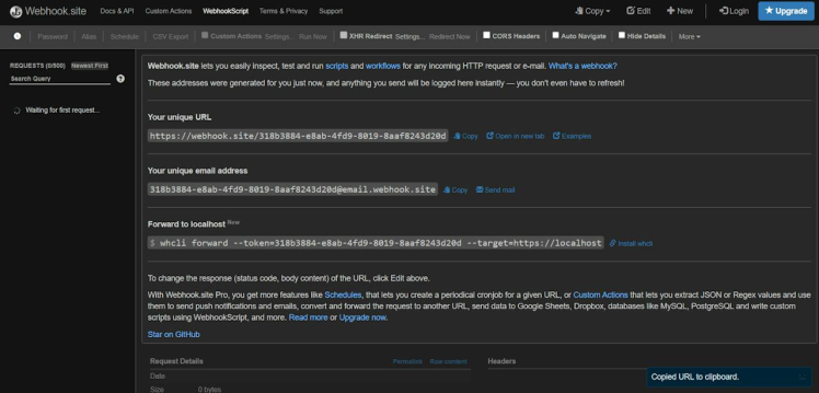
Then, I opened the webhook siteand copied the webhook URL.
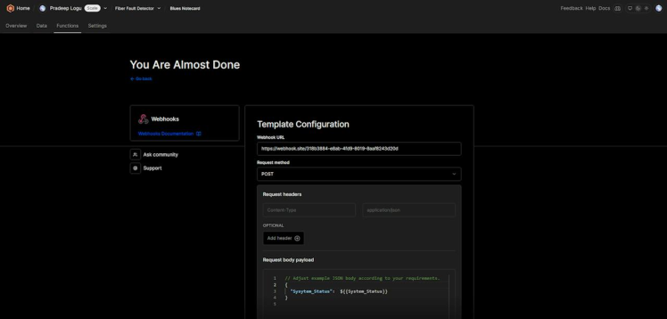
Next, I pasted the URL to the Qubitro rule page.
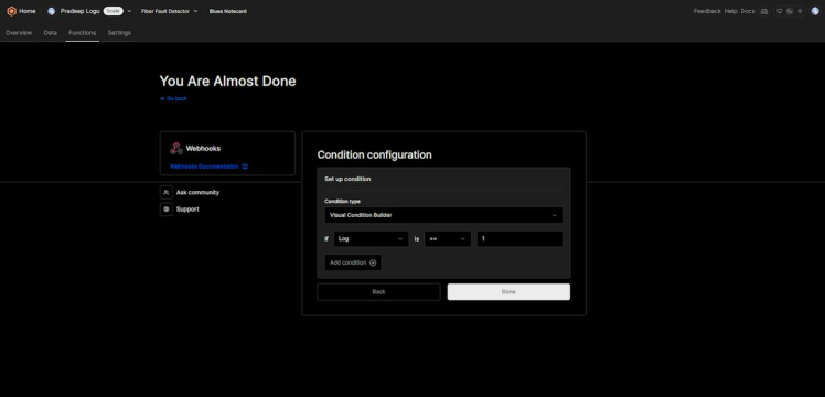
Then I selected the conditions. For this, my rule will trigger when my Log level is equal to 1.
Below is the webhook response.
Here you could use Twilio or Mailgun to send a customized SMS or email to alert you.
Conclusion
A Fiber Optic Network Cable Fault Alert Device is an essential tool in maintaining the health and functionality of a fiber optic network. By providing real-time alerts to faults, these devices can help prevent data loss, reduce downtime, and ultimately save money. Whether you’re a network administrator in a large corporation or a small business owner, investing in a Fiber Optic Network Cable Fault Alert Device could be a wise decision. Visit Blues Acceleratorsto get more interesting ideas and tutorials.
Credits
Related products


Leave your feedback...