
Fanduino - Cool Automatic Arduino Fan

Made by Ron / Home Automation / Robotics / Sensors
About the project
With the 4th of July here, the summer heat is in a full swing, and what better use for Arduino than to make a cool automatic fan.
Project info
Difficulty: Moderate
Estimated time: 1 hour
License: GNU General Public License, version 3 or later (GPL3+)
Items used in this project
Hardware components

Software apps and online services
Story
The Fourth of July is a time of joy, fireworks, the latest Independence Day movie, but also time of summer heat. So, it is only natural that while sweating it under the Californian sun I decided to post a tutorial for an Arduino controlled fan.
Step 1: Components
1 / 4 • Picture 1

Picture 1

Picture 2

Picture 3

Picture 4
Needed components:
- One Arduino (I use Mega because I have one available, but UNO is perfectly good for this project)
- One Breadboard
- One Texas Instruments LM35 Thermometer
- One Small Servo with a plastic arm (I used SG90 Servo)
- One Ultrasonic Ranger HC-SR04 or similar
- One large paperclip
- Few jumper wires
- One piece of paper to use for the flap
- Some Glue, and Adhesive Tape
Optional recommended components:
- 2 capacitors to reduce noise (I use 100 uF and 0.01 uF but you can use other values)
- One external power supply for the Servo. (You can power the servo with the Arduino board, but then there will be a lot of noise in the Thermometer readings)
1 / 10 • Picture 1

Picture 1

Picture 2

Picture 3

Picture 4

Picture 5

Picture 6

Picture 7

Picture 8

Picture 9

Picture 10
- Fold the paper flap through the center as shown in Picture 1
- Shape the paper clip into an asymmetric U shape, and insert the 2 ends through the Servo arm (Picture 2)
- Insert the 2 ends through the fold in the paper flap (Picture 3)
- Bend the paper clip as shown on Picture 4 and 5
- Secure the clip to the paper with Adhesive Tape (Picture 6)
- Apply glue to the paper (Picture 7)
- Glue the 2 inner sides of the paper together to form the flag as shown on Picture 8 and 9
1 / 6 • Picture 1

Picture 1

Picture 2

Picture 3

Picture 4

Picture 5

Picture 6
- Place the LM35 Thermometer on the Breadboard, and connect the Ground (Black wire), and Power (Red wire) to the power bus of the Breadboard as shown on Picture 1
- Optionally add a small capacitor between Ground and Power near the Thermometer, to reduce high frequency power noise as shown on Picture 2
- Optionally add a bigger capacitor between Ground and Power on the power bus to improve the power stability as shown on Picture 3
- Connect a wire (Green wire) to the middle pin of the Thermometer (Picture 4). This pin will output the analog temperature value measured by the LM35
- Connect Ground (Black wire) and Power (Red wire) wires to the power bus of the Breadboard to provide power from the Arduino Board (Picture 5)
- Connect the Temperature(Green wire) to the Arduino Analog 0 pin, the Power (Red wire) to the 5V Arduino Power pin, and the Ground (Black wire) to an Arduino Ground Pin (Picture 6)
1 / 2 • Picture 1

Picture 1

Picture 2
- Place the Ultrasonic Ranger on the Breadboard
- Connect the Power (Red wire), Ground (Black wire), Trigger (Yellow wire), and Ping/Echo (White wire) to the Ultrasonic Ranger. Connect the other end of the Power and Ground wires to the Power and Ground of the Power bus of the Breadboard (Picture 1)
- Connect the other end of the Trigger (Yellow wire) to Digital Pin 2 of the Arduino board, and Ping/Echo (White wire) to Digital Pin 3 of the Arduino board (Picture 2)
1 / 7 • Picture 1

Picture 1

Picture 2

Picture 3

Picture 4

Picture 5

Picture 6

Picture 7
For my Fan, I used external power for the Servo as recommended. It also reduces the power noise which affects the temperature measurements.
You can connect the Servo directly to the power of the Arduino board, but that is not recommended.
- Connect a jumper wire between the grounds of the two power buses on the breadboard as shown on Picture 1
- Add Ground (Black wire), Power (Red wire), and Control (Orange wire) to the Servo connector (Picture 2)
- Connect the other end of the Ground (Black wire), and Power (Red wire) to the separated power bus on the Breadboard (Picture 3) . If you decide to power the Servo directly from Arduino, connect to the same Breadboard power bus, where the Thermometer and the Ultrasonic Rangers are connected
- Connect the other end of the Control (Orange wire) to the Digital Pin 4 of the Arduino board (Picture 4)
- Add a Power Supply to the side of the breadboard where the Servo Power is connected (Pictures 5 and 6)
- Mount the Servo vertical using whatever convenient objects are around (In my case Spool of prototyping wire) (Picture 7)
1 / 4 • Picture 1

Picture 1

Picture 2

Picture 3

Picture 4
To start programming the Arduino, you will need to have the Arduino IDE installed from here: http://www.arduino.cc/ .
Please be aware that there are some critical bugs in Arduino IDE 1.6.6. Make sure that you install 1.6.7 or higher, otherwise this Tutorial will not work!
The Visuino: https://www.visuino.com also needs to be installed.
- Start Visuino
- From the Component Toolbox expand the "Measurement" Category, then the "Analog" Sub Category, and select the "Texas Instruments Thermometer LM35" component as shown on the first picture, and drop it in the design area
- From the Component Toolbox expand the "Math" Category, and select the "Average Period" component (Picture 2), and drop it in the design area. The Average component will help reduce noise by averaging multiple readings
- Connect the components as shown on Picture 3
- Set the Average Period to 100000 (Picture 4)
1 / 3 • Picture 1

Picture 1

Picture 2

Picture 3
- From the Component Toolbox expand the "Measurement" Category, then the "Analog" Sub Category, and select the "Ultrasonic Ranger" component as shown on the first picture, then drop it in the design area
- From the Component Toolbox expand the "Math" Category,and select the "Average Period" component, then you drop in in the design area, as you did with the Thermometer in the previous step. The Average component will help reduce noise by averaging multiple readings
- Connect the components as shown on (Picture 2)
- Set the value of the Period propertyof the AveragePeriod2 component to 2000000 (Picture 3)
1 / 4 • Picture 1

Picture 1

Picture 2

Picture 3

Picture 4
- From the Component Toolbox expand the "Motors" Category, and select the "Servo" component as shown on the first picture
- From the Component Toolbox expand the "Generators" Category, then the "Analog Generators" Sub Category, and select the "Sine Analog Generator" component as shown on the Picture 2, then drop it in the design area
- Connect the components as shown on Picture 3
- For the Sine Generator specify Amplitude of 0.3 (Picture 4)
1 / 2 • Picture 1

Picture 1

Picture 2
To Enable/Disable the Sine generator and control its frequency, we need to add pins to some of the properties:
- In the Object Inspector click on the Pin button at front of the Enabled property, and select "Boolean SinkPin" (Picture 1)
- In the Object Inspector click on the Pin button at front of the Frequency property, and select "Float SinkPin" (Picture 2)
1 / 10 • Picture 1

Picture 1

Picture 2

Picture 3

Picture 4

Picture 5

Picture 6

Picture 7

Picture 8

Picture 9

Picture 10
We want the temperature to control the speed of the fan. To do that we need to calculate frequency from the temperature.
- Type "subtr" in the Filter box of the Component Toolbox, then select the "Subtract Value" component (Picture 1), and drop it in the design area
- Type "mul" in the Filter box of the Component Toolbox, then select the "Multiply By Value" component (Picture 2), and drop it in the design area.
- In the Object Inspector set the Value of the Subtract component to 18 (Picture 3)
- In the Object Inspector set the Value of the Multiply component to 0.3 (Picture 4)
We also want to update the speed only once every 10 seconds. For this we will add a snapshot component and a clock component to send clock to the snapshot once every 10 seconds.
- Type "sna" in the Filter box of the Component Toolbox, then select the "Analog Snapshot" component (Picture 5), and drop it in the design area
- Type "clock" in the Filter box of the Component Toolbox, then select the "Clock Generator" component (Picture 6), and drop it in the design area.
- Connect the components as shown in Picture 7
- In the Object Inspector, set the value of the "Frequency" property of the Clock Generator to 0.1 (Picture 8) This way, the generator will generate a clock once every 10 seconds
- Connect the "Out" pin of the AnalogSnapshot1 component (Picture 9) to the "Frequency" input pin of the SineAnalogGenerator1 (Picture 10)
1 / 8 • Picture 1

Picture 1

Picture 2

Picture 3

Picture 4

Picture 5

Picture 6

Picture 7

Picture 8
- Type "compare" in the Filter box of the Component Toolbox, then select the "Compare Analog Value" component (Picture 1), and drop two of them in the design area
- In the Object Inspector for CompareAnalogValue1set the CompareType property to ctBigger and the Value property to 20 (Picture 2)
- In the Object Inspector for CompareAnalogValue2 set the CompareType property to ctSmaller and the Value property to 80 (Picture 3)
- Connect the Compare components as shown on Picture 4
- Type "and" in the Filter box of the Component Toolbox, then select the "Boolean And" component (Picture 5), and drop it in the design area
- Connect the "Out" pints of the CompareAnalogValue2 components to the inputs of the And1 component as shown in Picture 6
- Connect the "Out" pin of the And component (Picture 7) to the "Enabled" input property of the SineAnalogGenerator1 (Picture 8)
1 / 4 • Picture 1

Picture 1

Picture 2

Picture 3

Picture 4
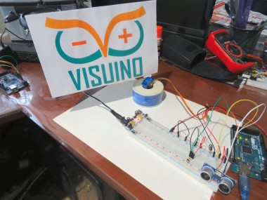
On the pictures you can see the completed fan.
To generate the Arduino code, press F9 in Visuino. This will generate the Arduino code, and will open the Arduino IDE, where you can compile and upload the code to the Arduino board. If you stand at front of the Sonic Ranger, and if the temperature in the room is above 20 degrees Celsius, the fan will start working. If the temperature gets higher, the fan will wave faster.
In Picture 4 you can see the complete Visuino connection diagram. You can change the starting temperature setting by modifying the Value property of the CompareAnalogValue1 component. You can change the starting distance from the Ultrasonic Ranger setting by modifying the Value property of the CompareAnalogValue2 component.
By changing the values of the SubtractValue1 and MultiplyByValue1 components you can adjust how the speed of the fan will depend on the temperature.
I have also attached the Visuino project for this Tutorial, as well as a PDF file with the Visuino flag. You can download and open the project in Visuino: https://www.visuino.com
Enjoy the cool!
Credits
Related products


Leave your feedback...