
Face Tracking Ping Pong Launcher With Arduino And Rpi

Made by Lmjd14 / 3D Printing / Artificial intelligence / Robotics / Security
About the project
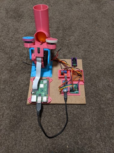
Protect your desk with this ping pong ball launcher that detects and aims at an intruder's face before firing a barrage of ping pong balls at them.
Project info
Difficulty: Moderate
Platforms: Arduino, Raspberry Pi, Python
Estimated time: 1 day
License: GNU General Public License, version 3 or later (GPL3+)
Items used in this project
Hardware components


View all
Hand tools and fabrication machines
Story
3D printing and assembling the launcher:
All of the 3D printed pieces can be found here: https://www.thingiverse.com/thing:5005516. You’ll need one of each piece except for Launcher Drums.stl, which you’ll need two of.
I designed all of these pieces with Tinkercad except for the raspberry pi case which came from https://www.thingiverse.com/thing:922740. As you can see by the file names, these pieces were the result of multiple iterations and versions. Some of the pieces can be printed fairly easily with no supports while some other pieces required supports. Motor Holder_Tube_Camera Holder_v2.stl in particular is a beast of a print. It took me about 14 hours with LOTS of supports as there isn’t really a good angle to print it at with limited supports. Everything was printed in PLA at 215 C and bed temp of 60C on an Ender 5 Pro. 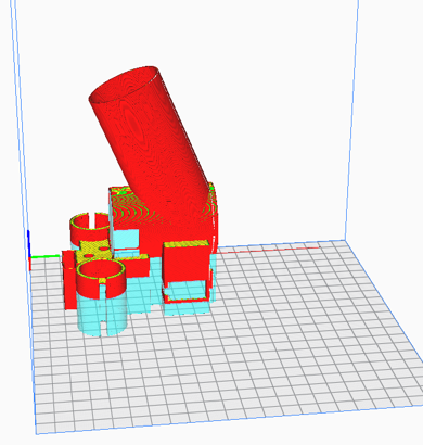
Motor Holder_Tube_Camera Holder_v2.stl set up to print with supports
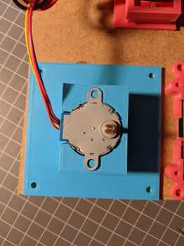
With all of the pieces printed, it’s time to assemble them. The first step is slotting the stepper motor into the base. This one is pretty easy. There’s only one way that it fits.
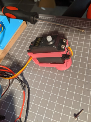
Next, we’ll put the servo into Servo Tilt Bracket - 5010_v2.3.stl. Check out the photos below for a guide. There are holes for four M3 bolts to secure it in place but I found that I only needed the top two. Also note the servo cord being tucked underneath the servo. This will help with cable management later on.
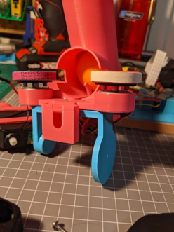
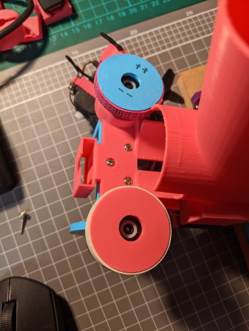
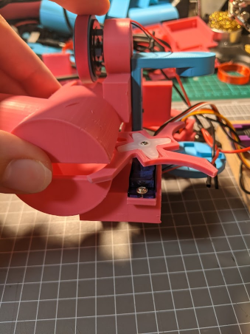
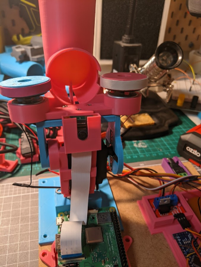
Now we put all the top pieces together. Motor Holder_Tube_Camera Holder_v2.stl is bolted to Servo Tilt Top v2.stl with 3 M3 bolts. The CD/DVD motors sit in the cavities on either side. The slit through the bottom gives the print a bit of flexibility to slot them in. The launcher drums then sit on top of the motors, with their four posts going through the corresponding holes on the motor. Now is also a good time to sit your rubber bands around the launcher drums. I found it necessary to stick them down with a little bit of super glue or else they fly off as the motors start to spin. If you need rubber bands that are the right size, I recommend taking a trip to the grocery store. My rubber bands started their lives holding together bunches of broccolini in the produce section.
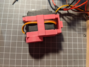
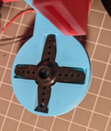
The continuous servo fits into the rectangular slot at the back, with the servo wire pointing TOWARDS the motor drums. The ball loader then sits between the servo and the four-arm servo horn that came with your servo. The supplied screw is then tightened to sandwich everything in place.
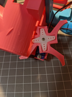
Connecting the top section to the tilt servo is a little bit fiddly. Put the four-arm servo horn from the 5050 servo into the crossed recess on the tilt top. Put the circular plug into the hole on the back side of the servo holder first. Then you should only need to bend the tilt top slightly to get the servo horn locked onto the servo. Finally, use the provided screw to tighten everything to the servo. It is very important when you do this that you make sure the servo is in the middle of its range. Once the top is connected, you should be able to rotate the top forwards and backwards to the point that they hit the servo on either side. If you hit the limit of the servo before you have a full range of motion, you’ll need to remove the top piece, and manually rotate the servo before trying again.
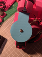
Lastly, the hole on the bottom of the servo should fit perfectly onto the shaft of the stepper motor. Since the stepper motor can rotate continuously, there’s no need with this one to put it on with any particular alignment.
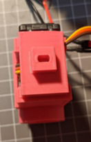
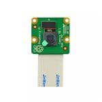
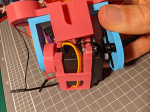
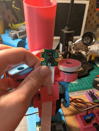
Now the launcher is connected, the only other thing to go on the launcher is the raspberry pi camera. Attach it by passing the camera ribbon through the slot at the bottom of the camera holder, then connecting the camera (blue side point towards the rest of the launcher), and then slotting the camera down into place.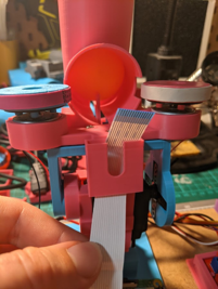
The remaining pieces are used to organise all of our electronics. They aren’t essential but I used it as a nice way to keep things organised and allowed me to glue everything down to a piece of MDF and keep everything neat.
Arduino Nano Wiring
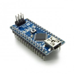
The arduino nano is doing all of the heavy lifting when it comes to controlling the launcher. The raspberry pi will be searching for faces and sending positions to the arduino via serial. Our arduino needs to listen for these messages and then have control over the stepper motor (pan), 5050 servo (tilt), launcher motors, and loading mechanism (continuous servo).
I have provided the wiring connections in two formats: a Fritzing diagram and a simple list of connections by component. Then there’s a few comments underneath for those interested in some of the choices I made.
Connection List
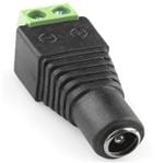
DC Barrel Jack
+5V -> Continuous servo VCC
+5V -> Tilt servo VCC
+5V -> Launch motors +ve
+5V -> Stepper motor controller VCC
+5V -> IRF520 VIN screw terminal
GND -> Continuous servo GND
GND -> TIlt servo GND
GND -> Arduino nano GND
GND -> Stepper motor controller GND
GND -> IRF520 GND screw terminal
Continuous servo
VCC -> Barrel jack +5V
GND -> Barrel jack GND
Signal -> Arduino D4
SG 5010 Tilt servo
VCC -> Barrel jack +5V
GND -> Barrel jack GND
Signal -> Arduino D5
Launch Motors
Positive -> IRF520 V+ screw terminal
Negative -> IRF520 V- screw terminal
Note: Positive and negative don’t mean much here as the two motors are connected together positive to negative and vice versa so that one rotates CW, and the other one CCW. Just try the wires both ways and pick the one that spins the left motor CW and the right motor CCW when viewed from the top.
IRF520
VIN screw terminal -> Barrel jack +5V
GND screw terminal -> Barrel jack GND
V+ -> Launch motor positive
V- -> Launch motor negative
VCC pin -> Arduino 5V pin
GND pin -> Arduino GND pin
SIG pin -> Arduino D6
Stepper Motor Controller
+VCC -> Barrel jack +5V
-GND -> Barrel jack GND
IN1 -> Arduino D8
IN2 -> Arduino D9
IN3 -> Arduino D10
IN4 -> Arduino D11
Arduino Nano
D4 -> Continuous servo signal
D5 -> Tilt servo signal
D6 -> IRF520 signal
D8 -> Stepper controller IN1
D9 -> Stepper controller IN2
D10 -> Stepper controller IN3
D11 -> Stepper controller IN4
GND -> Barrel jack GND
GND -> IRF520 GND pin
5V -> IRF520 5V pin
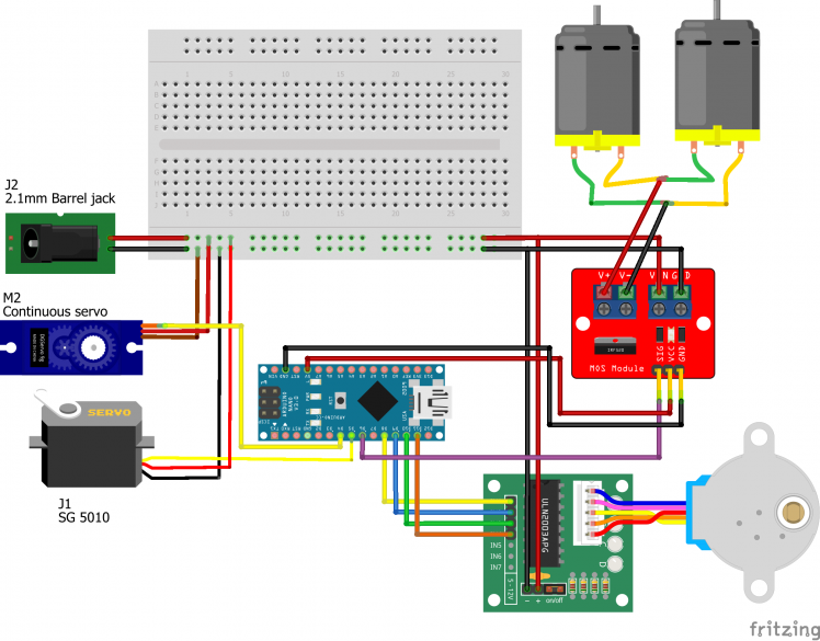
Wiring diagram
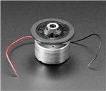
There were a few interesting points I learnt along the way. I originally tried coreless drone motors for the launcher drums but couldn’t 3D print holes small enough to fit on the shaft. Instead, I found an adafruit project for a ping pong ball launcher (https://learn.adafruit.com/ping-pong-ball-launcher-with-cpx/launch-ping-pong-balls) where they used a CD spindle motor. They seemed quieter and more stable than other motors and came ready with a premounted top piece that allowed me to easily attach 3D printed add-ons.
The other interesting design choice that I needed to change was the use of a transistor instead of a MOSFET to control the launcher motors. After wiring up the entire circuit, I found that the motors didn’t spin or spun intermittently when the transistor was switched on. Turns out your average transistor can’t handle enough current to drive the motors. Fortunately I had a MOSFET module sitting around which ended up working perfectly!
Coding the arduino
All code for this project is available from github: https://github.com/lmjd14/PingPongLauncher
The arduino nano can control all of the motors/servos on the launcher but it doesn’t know where the target’s face is. The arduino is coded to listen for serial commands, interpret them, and perform the requested motion. This also gave me a chance to try out something new when I defined a bunch of useful functions and variables in a separate header file.
The control.h file is where you’ll find a bunch of useful settings like the pin numbers for various components, the stepper motor speed, and the speed and time used to load the ball with a continuous servo (we’ll discuss this a bit later). The main body of this file however is a series of functions that allow us to pan, tilt, toggle launch motors on/off, and load a ball. These are all fairly self explanatory but by putting them in functions, it’s much easier to call them from the main routine. I will however note a few interesting points in these functions.
Each function executes the required move and then writes a single character to serial based on the move that just happened (‘p’ for pan, ‘t’ for tilt, etc.). This occurs after the move has happened so it acts as a way of telling the raspberry pi that it is finished after each move.
The most interesting function is the load function and this is one that you may need to fiddle with to get working correctly. Continuous servos don’t go to specified angles but rather they can be set to rotate at a fixed speed. Writing a 0 to the servo rotates it full speed backwards. 90 should be stopped (for my servo, a value of 89 was needed for it to be stopped), and 180 is full speed forwards. Then you can interpolate between these points if you want but we’ll operate at max speed. Since we can’t command an exact position, we have to set a particular speed and then let the servo run for a given amount of time to load a single ball. That is why we define LOAD_SPEED and LOAD_TIME at the top of control.h. My settings of these two parameters worked for my particular servo but you may need to fine tune the LOAD_TIME to get your launcher turning just enough to load a single ball each time. An extra note about this process, I have used the “delay” function to make the servo run for the right amount of time. This function is often maligned as inferior to the millis() function but it’s also faster, easier, and good enough for this application.
The other interesting part of this function is that we attach and detach the servo each time the load function is called. I found that with the servo connected all the time, it sometimes kept rotating when it should be stopped, or when it did stop, it occasionally moved forwards/backwards randomly (I think this may have been due to noise from the power supply or the arduino pin but can’t be sure). To ensure that the servo stayed still when it was stopped, I disconnected it so it could not receive any signals to move. This worked well and the time to attach/detach the servo pin isn’t enough to cause any delays in the loading process.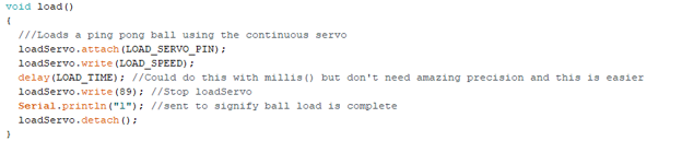
Load function with servo detachment
PingPongLauncherControl is the code that actually calls all of the functions in the header file as it listens for instructions over serial. Most things in the setup() loop should be self explanatory. The only interesting line here is “Serial.setTimeout(250);” Later on, we’ll be listening for a string from the raspberry pi. Arduino’s serial library has an inbuilt timeout of 1000ms. If we keep this timeout, reading the serial output takes 1 second per command. That would mean we could only update one axis of our launcher once every second which is way too slow! I actually solved this problem in another way later on but the timeout is nonetheless shortened as a backup in case something goes wrong with the other method.
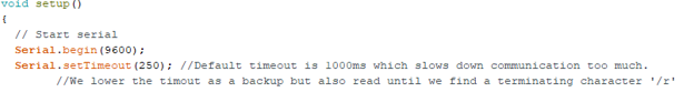
Shortening the Serial timeout to speed up the launcher’s update rate.
The loop() function has two main steps:
- Listen for new serial commands
- Interpret these commands and execute the requested motion
While listening for commands, I have used the Serial.readStringUntil() function which helps us overcome the timeout issues discussed above that would have hurt me if I only used the Serial.readString() function. For this function, I specifically tell the arduino to listen for a carriage return to know when we’ve reached the end of the command. You could change this character to something more exciting like a “@” or “#” if you wanted. In that case, you’d just have to append that character to the messages sent by the raspberry pi.
After the message is received, it is interpreted to know how the launcher is meant to move. There’s nothing too exciting here but I have left in some commented lines in case you want to test the code out and see what is being received and interpreted by the arduino. You’ll notice that this interpretation is a series of if/else statements. This means we can only send one command at a time (e.g. pan10 to pan 10 degrees instead of something like pan10tilt110motor1 to pan 10 degrees, tilt to 110 degrees, and turn the motors on). While this theoretically slows down the process as you have to send more messages to the arduino, it is still much faster than the slow step of image processing on the pi so I left it as is for simplicity. One potential improvement would be to send a message of fixed format (‘panXXtiltYYYmotorZ/r’) and deconstruct it so that all axes could be adjusted at once.
That’s it for the arduino code! Now to upload it. If you’re using a cheap arduino clone for the first time or recently changed computers like me, remember to install the CH340 drivers you can find here (https://learn.sparkfun.com/tutorials/how-to-install-ch340-drivers/all), and try using the old bootloader (Tools -> Processor ->ATmega328P (Old bootloader)) if you have upload problems.
Coding the Raspberry Pi
The code for the raspberry pi is written in python and is generally based off a similar project you can find here (https://www.pyimagesearch.com/2019/04/01/pan-tilt-face-tracking-with-a-raspberry-pi-and-opencv/) but is a little less complex (if I do say so myself) and uses different hardware. Again, it is all available on github here (https://github.com/lmjd14/PingPongLauncher)
The code for this project is split between a few different files to keep the individual files from getting too large and cluttered. I’ll go through them one by one:
faceDetect.py
This is a very short file containing only one function. It detects faces in an image and reports the position of the face’s centre. The face detection is done with openCV. You can install this library using pip like most other python libraries but note that the library is referred as openCV, the import statement for it is import cv2, and the install command is pip install opencv-python.
Face detection is done using a Haar cascade, which is a pre-trained machine learning classifier for detecting faces. The classifier we use is stored in an xml file and is called haarcascade_frontalface_default.xml. This classifier is used to detect faces in a provided image using the detectMultiScale() method. The arguments used in this method were based off recommended values I found in examples online and I found that I didn’t have to change them to get a good result. It is important to note that the cascade that we used is only designed to identify faces when viewed front-on. There are a variety of different Haar cascade files included in openCV that you can substitute into this code to instead identify eyes, torsos, smiling faces, cats, trees, russian license plates, and more…
If a face is detected, this function returns the X and Y coordinates of the face, and a list with some extra details about the face. When we find more than one face, we only keep details about the first one found because aiming at two things at once is too hard. If no faces are detected, we just return a whole lot of None.
panTiltControl.py
This file is a little more beefy. The first thing defined here is a Launcher class that basically acts as a python wrapper for all of our arduino functions to control the launcher. We need to initialise it with a serial port to tell the raspberry pi where to look for the arduino. When you plug the arduino into a USB port on the pi, you can open a terminal on the pi and use a command like “ls /dev/*USB*” to list out the connected USB ports. If the arduino is the only thing connected, hopefully the USB port is “/dev/ttyUSB0” which is the default used for this class.
In the methods for the class, note that the commands are built using the structure we are searching for on the arduino (e.g. pan10 to pan to 10 degrees) and have a carriage return at the end as this is the terminating character that the Serial.readStringUntil() function is looking for on the arduino. Once the command is sent, we also wait to hear back from the arduino. This ensures that we don’t send too many commands at once and cause the arduino to miss a command.
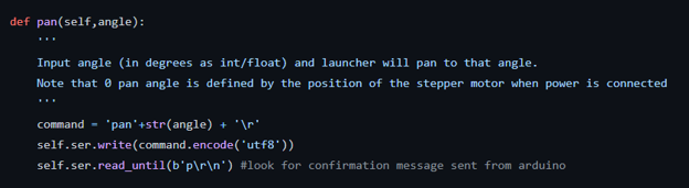
An example of a command to communicate with the arduino from a raspberry pi
The other part of this file is a PID class. This class allows us to create PID controllers with varying P, I, and D constants. There are lots of good tutorials out there describing how PID controllers work so I won’t go into it here any more than by saying that they allow you to calculate how best to change an input to reach a desired output. This PID class allows us to set our PID constants and then the update method calculates the current error that we’ll use to determine how much to move out launcher by.
trackAndLaunch.py
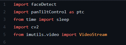
This is the main script that we’ll be running when our launcher is working. First we import the files we just discussed (make sure they’re saved in the same folder) along with a few other helpful libraries.
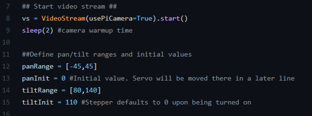
Next, we create a video stream which can be set to automagically find and use the raspberry pi camera. Below this, you can also define an allowed range and initial value for the pan and tilt axes. The allowed range sets where the launcher can move without crashing and the launcher will be sent to the initial values upon the code starting.
The path to the haarcascade file is set to the openCV library’s internal copy on line 22 so you don’t need to keep a copy of the .xml file that is on github in the working directory.
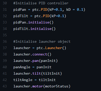
We then initialise two PID controllers. There is one PID controller calculating the required motion of the panning stepper motor and another for the tilt servo. If you want to use PID constants other than the defaults, they can be defined here. An instance of the Launcher class is also initialised and set to the initial positions we defined in the panTiltTrack.py file.
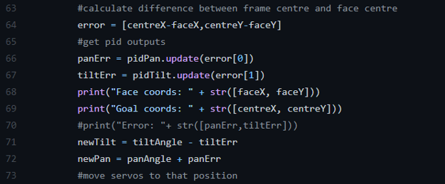
The ongoing routine then occurs in an infinite while loop. I take a frame from the video stream and find a face using the findFace function from faceDetect.py. If a face is found, we add some text to the output saying “INTRUDER DETECTED”. The X and Y distance between the face and the centre of the image is calculated and used as the error inputs to our two PID controllers. These PID controllers return new pan and tilt angles for us to send to the arduino. Note that we add the error to error to the pan angle while subtracting it from the tilt angle to make sure both stages move in the right direction and correct the error instead of making it worse.
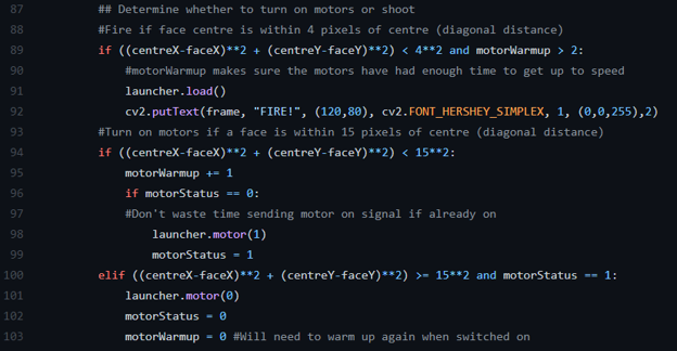
If we calculate the error between the face position and image centre and find that it is less than 15 pixels (measured diagonally using the Pythagorean theory), we are getting close so it is worth turning on the motors to make sure they are ready to fire. When the distance between the image centre and face centre is less than 4 pixels, it’s time to fire and we tell the arduino to load a ball. We also add some more text to the image for the fun of it :)
Along the way, we display the current frame and put a box around any faces we find. Here’s an example of what a frame might look like when the launcher is lined up
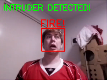
An example of the video tracking output when a face is lined up in the middle of the view
Now initially, I didn’t expect that lining up a face in the exact middle of the frame would lead to a direct hit. I assumed the ball would consistently shoot too low/high, or to the left or right. Fortunately, I found that the aim for my launcher was already bang on so as long as the face is in the middle of the image, you’re probably going to hit. My sore nose can attest to that fact!
I also initially thought that I would have to account for gravity and potentially figure out how far away the face was to know how far it would drop over that time. I was again fortunate and found that within about 2 metres of the launcher, the ball is travelling so fast that the parabolic trajectory can be approximated as a straight line. Given that I didn’t see a use case for the launcher beyond that range, it meant I got to approximate away my problems and just forget about them! If you wanted to shoot further, you’d have to figure out the distance to the person (I toyed with the idea of calculating the size of the face and comparing that to an average face size to estimate the distance of a person. I assume this would be hard and require finding a camera calibration matrix for your camera) and potentially account for any spin that the motors impart in case one motor spins faster than the other. This would also give your targets more time to react and dodge which is less fun.
Now there’s only one part left before you’re fully up and running. The PID controllers will hopefully work fairly well with the PID constants that I used but they might need to be tuned for your particular system. I recommend the following method:
- Set kP = 0.01, kI = 0, and kD = 0. This should produce a controller that takes tiny steps towards the centre.
- Slowly increase kP until the stages start oscillating on either side of the intended position, then reduce them back down a little bit again (the kP values will be different for both panning and tilting).
- This on its own will take a long time to reach the centre when you start far away. Slowly increase kD until you can get near the centre quickly when a face starts near the edge of the frame.
- I found that I didn’t need an integration step in my controller so kI stayed at 0.
Conclusion
That’s it! You’re done! Hopefully everything works for you and I’ve added a few potential improvements to give you a bit of a challenge if you’re interested. Good luck!
CAD, enclosures and custom parts
Code
Credits
Related products


Leave your feedback...