
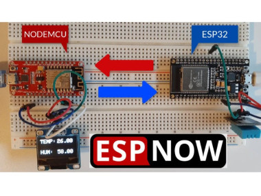
Espnow Peer To Peer Esp32 &esp8266 Simple Wifi Communication

Made by Ron / Communication / Displays / Sensors / IoT
About the project
In this project you will learn how easy it is to send data between two ESP Boards using the ESPNOW - Peer to Peer Wireless Communication
Items used in this project
Hardware components

Story
- 2X ESP32 or ESP8266 (It can be any ESP board)
- DHT11 Temperature & Humidity sensor (or any other DHT sensor)
- OLED Display
- Jumper wires
- Breadboard
- Visuino program: Download Visuino

Thank you PCBWay for supporting this tutorial and helping users learn more about electronics.
What I like about the PCBWay is that you can get 10 boards for approximately $5 which is really cost effective for professional made boards, not to mention how much time you save!
Go check them out here. They also offer a lot of other stuff in case you might need it like assembly,3D printing,CNC machining and a lot more.
Step 3: The Circuit1 / 2
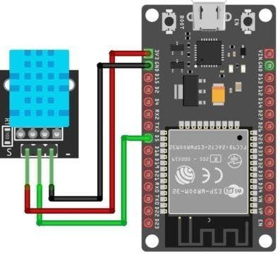
ESP32:
- Connect DHT11 VCC pin to the 5V output on the ESP32 and connect GND to ground.
- Connect DHT11 PIN S (Signal) to ESP32 Pin GPIO 5
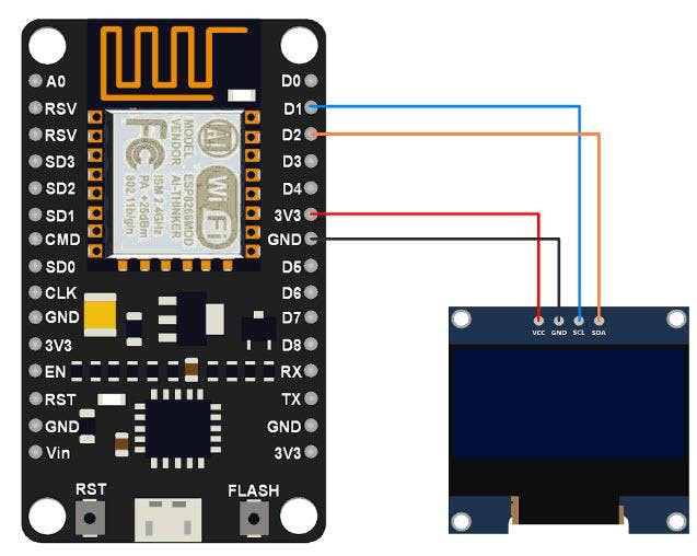
NodeMCU:
- Connections are fairly simple. Start by connecting VCC pin to the 3.3V output on the NodeMCU and connect GND to ground.
- Connect the OLED SCL pin to the I2C clock D1 pin on your NodeMCU and connect the OLED SDA pin to the I2C data D2 pin on your NodeMCU.
1 / 4
The Visuino: https://www.visuino.eu also needs to be installed. Download Free version or register for a Free Trial.
Repeat this step for both ESP boards:
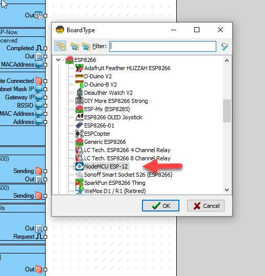
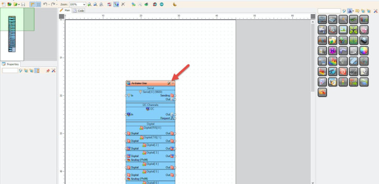
- Start Visuino as shown in the first picture Click on the "Tools" button on the Arduino component (Picture 1) in Visuino When the dialog appears, select "ESP32" or "NODEMCU" Or any other ESP board that you use.
- Connect pin MAC Address to Serial Pin [0] as on (Picture 2)
- In Visuino, at the bottom click on the "Build" Tab, make sure the correct port is selected, then click on the "Compile/Build and Upload" button.
- Then click on the "Serial" Tab and click on the button "Connect"
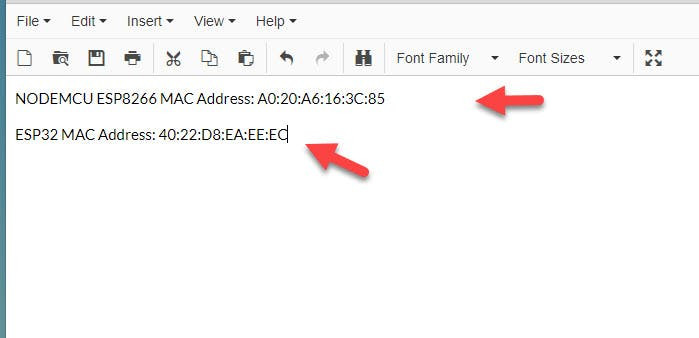
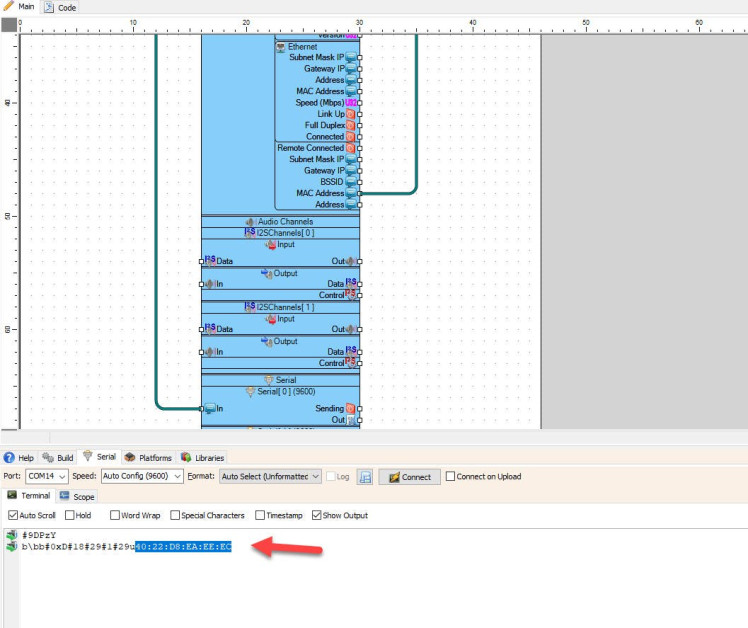
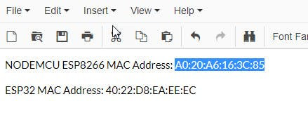
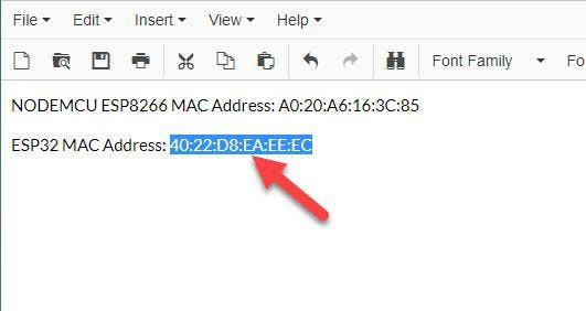
- You should see the MAC Address as on (Picture 3), In case you do not see it, click the "Reset" button on the ESP Board
- Copy the MAC Address to your Notepad as on (Picture 4)
The Visuino: https://www.visuino.eu also needs to be installed. Download Free version or register for a Free Trial.
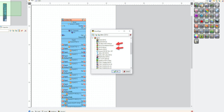
Start Visuino as shown in the first picture Click on the "Tools" button on the Arduino component (Picture 1) in Visuino When the dialog appears, select "ESP32" as shown on Picture 2
Step 6: For Sender ESP32 - in Visuino Add, Set & Connect Components1 / 10
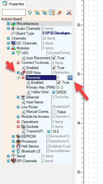

- Select the "ESP32 Development Board" board and in the Properties window extend Modules>WiFi>ESP-NOW>Elements and click on the 3 dots Button
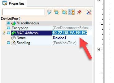
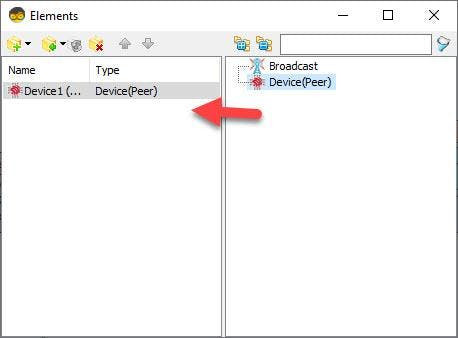
- In the Elements window Drag "Device(Peer)" to the Left side and in the Properties window paste the MAC Address of the other Board in our case NODEMCU
- Close the Elements Window
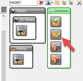
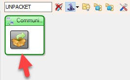
- Add "Packet" component
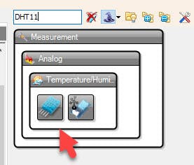
- Add "DHT11" component
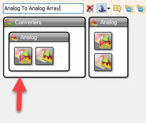
- Add "Analog To Analog Array" component
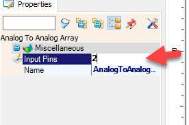
- Select "AnalogToAnalogArray1" and in the Properties window set "Input Pins" to 2
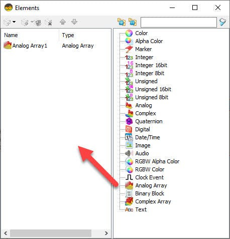
- Double click on the "Packet1" and in the Elements window Drag "Analog Array" to the Left side
- Close the Elements Window
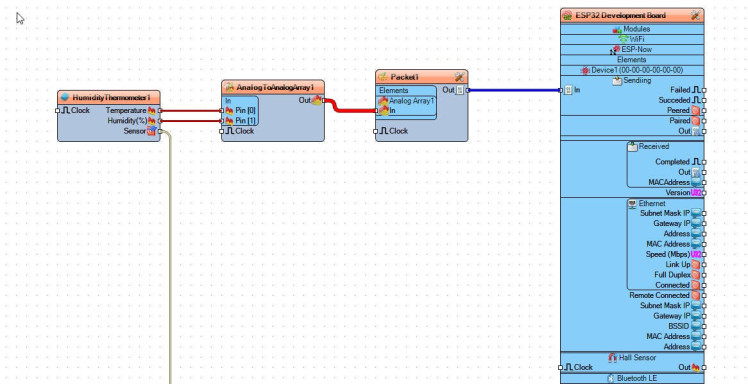
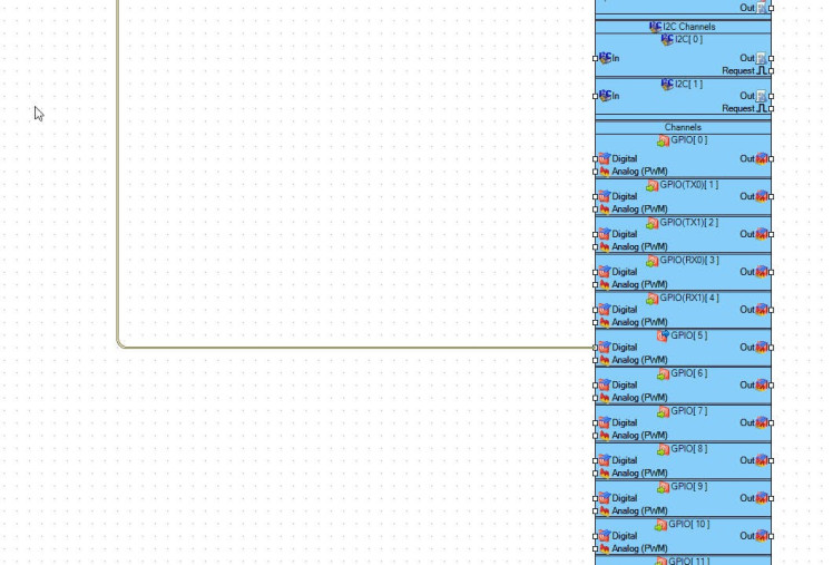
- Connect "HumidityThermometer1" Pin [Sensor] to "ESP32 Development Board" Digital Pin [GPIO 5]
- Connect "HumidityThermometer1" Pin [Temperature] to "AnalogToAnalogArray1" Pin [0]
- Connect "HumidityThermometer1" Pin [Humidity] to "AnalogToAnalogArray1" Pin [1]
- Connect "AnalogToAnalogArray1" Pin [Out] to "Packet1" > "Analog Array1" Pin [In]
- Connect "Packet1" Pin [Out] to "ESP32 Development Board" Digital Pin [Sending]
Upload the Project to the Arduino Board (see the Generate, Compile, and Upload the Arduino Code step)
Step 7: Receiver NODEMCU : Start Visuino, and Select the NODEMCU Board Type
The Visuino: https://www.visuino.eu also needs to be installed. Download Free version or register for a Free Trial.
Start Visuino as shown in the first picture Click on the "Tools" button on the Arduino component (Picture 1) in Visuino When the dialog appears, select "NodeMCU ESP-12" as shown on Picture 2
Step 8: For Receiver NODEMCU - in Visuino Add, Set & Connect Components1 / 16
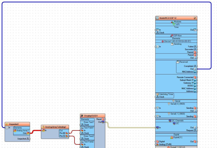
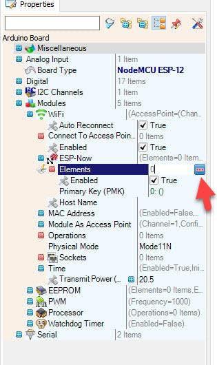

- Select the "NodeMCU ESP-12" board and in the Properties window extend Modules>WiFi>ESP-NOW>Elements and click on the 3 dots Button
- In the Elements window Drag "Device(Peer)" to the Left side and in the Properties window paste the MAC Address of the other Board in our case ESP32
- Close the Elements Window
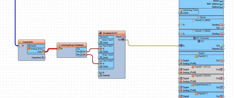
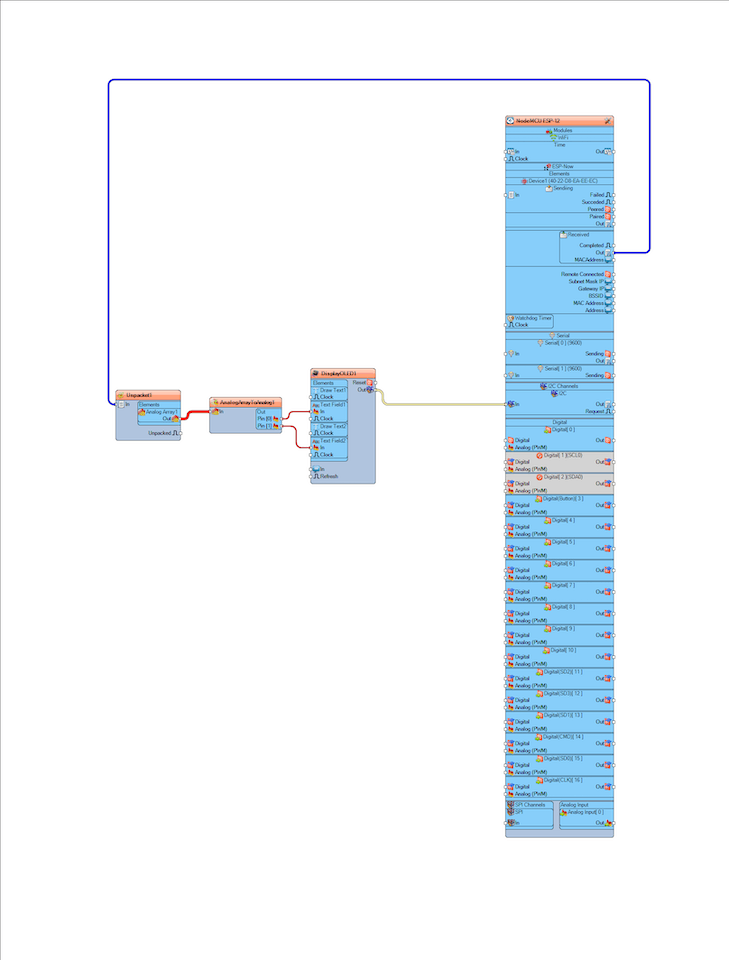
- Add "UnPacket" component
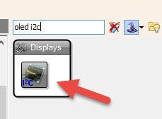
- Add "OLED I2C" component
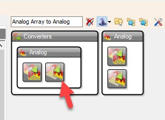
- Add "Analog Array to Analog" component
- Select "AnalogArrayToAnalog1" and in the Properties window set "Output Pins" to 2
- Double click on the "UNPacket1" and in the Elements window Drag "Analog Array" to the Left side
- Close the Elements Window
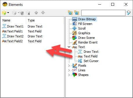
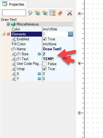
- Double click on the "DisplayOLED1" and in the Elements window Drag "DrawText" to the Left side & in the Properties window set "Text" to TEMP and "Size" to 2
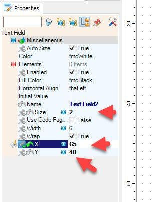
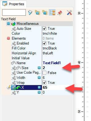
- In the Elements window Drag "Text Field" to the Left side & in the Properties window set "Size" to 2, "X" to 65
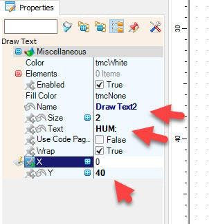
- In the Elements window Drag "DrawText" to the Left side & in the Properties window set "Text" to HUM and "Size" to 2, "Y" to 40
- In the Elements window Drag "Text Field" to the Left side & in the Properties window set "Size" to 2, "X" to 65 and "Y" to 40
- Close the Elements Window
- Connect "NodeMCU ESP-12" board Pin Received [Out] to "Unpacket1" Pin [In]
- Connect "Unpacket1" > "Analog Array1" Pin [Out] to "AnalogArrayToAnalog1" Pin [In]
- Connect "AnalogArrayToAnalog1" Pin [0] to "DisplayOLED1" > "Text Field1" Pin [In]
- Connect "AnalogArrayToAnalog1" Pin [1] to "DisplayOLED1" > "Text Field2" Pin [In]
- Connect "DisplayOLED1" Pin I2C [Out] to "NodeMCU ESP-12" board Pin I2C [In]
Upload the Project to the Arduino Board (see the Generate, Compile, and Upload the Arduino Code step)
Step 9: Generate, Compile, and Upload the Code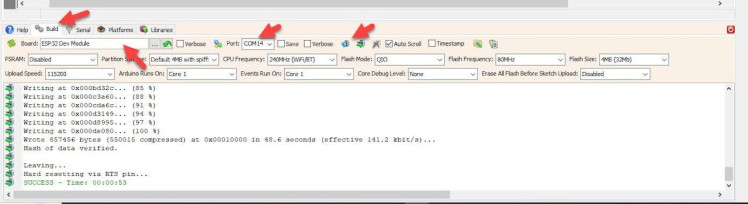
In Visuino, at the bottom click on the "Build" Tab, make sure the correct port is selected, then click on the "Compile/Build and Upload" button.
Step 10: PlayIf you power the ESP modules, you should start to see on the OLED Display the Temperature & Humidity received from the other ESP board.
Congratulations! You have completed your project with Visuino. Also attached are the Visuino project files for Sender and Receiver, that I created for this Tutorial, you can download it and open it in Visuino: https://www.visuino.eu
Schematics, diagrams and documents
Code
Credits
Related products


Leave your feedback...