
Esp8266 Wi-fi: Remote Control Servo With Rotary Encoder

About the project
Control servo remotely over Wi-Fi with rotary encoder - Quick and Easy!
Items used in this project
Hardware components

Software apps and online services
Story
ESP8266 modules are great low-cost stand alone controllers with built in WiFi. In this tutorial I will show you how you can control a Servo remotely over WiFi with a Rotary Encoder. The tutorial is a similar but more advanced version of the "Arduino Nano and Visuino: Control Servo with Rotary Encoder" tutorial.
In the tutorial, I will use 2 NodeMCU modules. One version 0.9, and the other 1.0. The NodeMCU are the easiest way to program and experiment with ESP8266 controllers. This tutorial however, can easily be done with other modules, and the Servo module can even use ESP-01 module as it needs only one GPIO pin to connect to the Servo.
Components

Components
Connect the Rotary Encoder to the First NodeMCU
1 / 4 • Picture 1

Picture 1

Picture 2

Picture 3

Picture 4
- Connect the Ground (Black wire), Power (Red wire), Direction (Green wire), Clock (Yellow wire), and Switch wire (White wire) to the Rotary Encoder Module (Picture 1)
- Connect the other end of the Ground (Black wire) to Ground pin of the ESP8266 NodeMCU module (Picture 2).
- Connect the other end of the Power (Red wire) to the 3.3V power pin of the ESP8266 NodeMCU module (Picture 2)
- Connect the Clock (Yellow wire) to Digital pin 2 of the ESP8266 NodeMCU module (Picture 3)
- Connect the Direction (Green wire) to Digital pin 3 of the ESP8266 NodeMCU module (Picture 3)
- Connect the Switch (White wire) to Digital pin 4 of the ESP8266 NodeMCU module (Picture 3)
- Picture 4 shows where are the Ground, 3.3V Power, Digital 2, Digital 3, and Digital 4 pins of the NodeMCU 1.0
1 / 4 • Picture 1

Picture 1

Picture 2

Picture 3

Picture 4
To simplify this tutorial, we will connect the Power from the NodeMCU to the Servo. In real projects, you will need to have a dedicated power supply for the servo! Please look at this tutorial to see how you can connect the Servo to external power.
- Connect the Ground (Black wire), Power (Red wire), and Control (Orange wire) to the Servo (Picture 1)
- Connect the other end of the Power wire (Red) to the 5V (Called "Vin" in NodeMCU version 1.0) Power pin of the ESP8266 NodeMCU module (Picture 2)
- Connect the other end of the Ground wire (Black) to the Ground pin of the ESP8266 NodeMCU module (Picture 2)
- Connect the other end of the Control wire (Orange) to the Digital pin 2 of the ESP8266 NodeMCU module (Picture 3)
- Picture 4 shows where are the Ground, 5V (Vin) Power, and Digital 2 pins of the NodeMCU 0.9
1 / 2 • Picture 1

Picture 1

Picture 2
Make sure that you install Arduino IDE 1.6.7 or higher, otherwise this Tutorial will not work!
If you have not done follow the steps in this Tutorial to setup the Arduino IDE to program ESP 8266!
- Start Visuino as shown in the first picture
- Click on the "Tools" button on the Arduino component (Picture 1) in Visuino
- When the dialog appears, select "NodeMCU ESP-12" as shown on Picture 2
1 / 3 • Picture 1

Picture 1

Picture 2

Picture 3
- In the Object Inspector, expand the "Modules" property, then the "WiFi" sub property, then the "AccessPoint: sub property" (Picture 1)
- Set the value of the "SSID" sub property of the "AccessPoint", to “ServoRemote” (Picture 1)
To make sure the Access Point will be on the 200.200.200.X subnet, we need to assign a fixed address.
- In the Object Inspector, expand the "Config" sub property of the "AccessPoint" property (Picture 2)
- Set the value of the “Enabled” sub property of the Config to “True” (Picture 2)
- Set the value of the “IP” sub property to "200.200.200.100" (Picture 3)
1 / 4 • Picture 1

Picture 1

Picture 2

Picture 3

Picture 4
Next we need to add an UDP socket for the communication.
- In the Object Inspector, click on the "..." button next to the value of the "Sockets" sub property of the "WiFi" property (Picture 1)
- In the Sockets editor select “UDP Socket”, and then click on the "+" button (Picture 2)
-
In the Object Inspector, set the value “
RemoteIPAddress” property to “200.200.200.200” (Picture 3) – this is the fixed IP address that we will assign to the other module later on
-
In the Object Inspector set the value of the “
RemotePort” to “8888” (Picture 4)
- Close the "Sockets" editor.
1 / 3 • Picture 1

Picture 1

Picture 2

Picture 3
- Type "rotar" in the Filter box of the Component Toolbox then select the "Rotary Encoder Sensor" component (Picture 1), and drop it in the design area
- Connect the "Out" pin of the Digital[ 2 ] channel of the "NodeMCU ESP-12"component to the "Clock(A)" pin of the RotaryEncoderSensor1 (Picture 2)
- Connect the "Out" pin of the Digital[ 3 ] channel of the "NodeMCU ESP-12"component to the "Direction(B)" pin of the RotaryEncoderSensor1 (Picture 3)
1 / 6 • Picture 1

Picture 1

Picture 2

Picture 3

Picture 4

Picture 5

Picture 6
We need a counter to count the Up/Down rotations from 0 to 100, and we need to set in in the middle/neutral 50:
- Type "count" in the Filter box of the Component Toolbox then select the "Up/Down Counter" component (Picture 1), and drop it in the design area
- In the Object Inspector set the value of the InitialValue property to 50 (Picture 2)
- In the Object Inspector expand the Counter's Min property
- In the Object Inspector set the value of the RollOver sub property to False (Picture 3)
- In the Object Inspector set the value of the Value sub property to 0 (Picture 3)
- In the Object Inspector expand the Counter's Max property (Picture 5)
- In the Object Inspector set the value of the RollOver sub property to False (Picture 5)
- In the Object Inspector set the value of the Value sub property to 100 (Picture 6)
1 / 4 • Picture 1

Picture 1

Picture 2

Picture 3

Picture 4
- Connect the "Down" pin of the RotaryEncoderSensor1 component to the "Down" pin of the UpDownCounter1 component (Picture 1)
- Connect the "Up" pin of the RotaryEncoderSensor1 component to the "Up" pin of the UpDownCounter1 component (Picture 2)
- Connect the "Out" pin of the" Digital[ 4 ]" channel of the "NodeMCU ESP-12" component to the "Reset" pin of the UpDownCounter1 (Picture 3)
The Rotary encoder module switch that I have does not have pull up resistor. The ESP8266 however has built-in optional pull-up resistors for the pins. To enable the pull-up resistor for the Digital pin 4:
- In the Object Inspector expand the "Digital" property, then the "Digital[ 4 ]" sub property (Picture 4)
- In the Object Inspector set the value of the IsPullUp sub property to True (Picture 4)
1 / 3 • Picture 1

Picture 1

Picture 2

Picture 3
The servo needs analog value in the range between 0 and 1.0, so we need to convert the count to Analog and multiply it by 0.01 to convert the 0 to 100 range into Analog 0 to 1.0:
- Type "To Analo" in the Filter box of the Component Toolbox then select the "Integer To Analog" component (Picture 1), and drop it in the design area
- In the Object Inspector set the Scale property to 0.01 (Picture 2) . This will convert the counter values from the integer range of 0 to 100, to the analog range of 0.0 to 1.0.
- Connect the "Out" pin of the UpDownCounter1 to the "In" pin of the IntegerToAnalog1 component (Picture 3)
1 / 4 • Picture 1

Picture 1

Picture 2

Picture 3

Picture 4
We need to send the analog value over the UDP. To do that we will make a structure with analog value and will send it over the UDP socket.
- Type "make" in the Filter box of the Component Toolbox then select the "Make Structure" component (Picture 1), and drop it in the design area
- Click on the "Tools" button (Picture 2) to open the "Elements" editor (Picture 3)
- In the "Elements" editor select the “Analog” element, and then clickon the "+" button (Picture 3) to add an Analog element (Picture 4)
- Close the "Elements" editor.
1 / 3 • Picture 1

Picture 1

Picture 2

Picture 3
- Connect the “Out” pin of the MakeStructure1 component to the “In” pin of the "Modules.WiFi.Sockets.UDPSocket1” of the “NodeMCU ESP-12” component (Picture 3)
- Connect the the “In” pin of the “Elements.Analog1” element of the MakeStructure1 component to the "Out" pin of the IntegerToAnalog1 component (Picture 3)
1 / 2 • Picture 1

Picture 1

Picture 2
- In Visuino, Press F9 or click on the button shown on Picture 1 to generate the Arduino code, and open the Arduino IDE
- Connect the first NodeMCU module (The one with the Rotary Encoder) with USB cable to the computer
- Select the board type and serial port as I have shown you in this tutorial
- Make sure you have installed the latest staging version of the ESP support! The stable release does not have some of the latest features, and you will have errors when you try to compile!
- In the Arduino IDE, click on the Upload button, to compile and upload the code (Picture 2)
1 / 5 • Picture 1

Picture 1

Picture 2

Picture 3

Picture 4

Picture 5
Now lets program the Servo module.
- Start new project.
- Click on the "Tools" button on the Arduino component, and when the dialog appears, select "NodeMCU ESP-12" as you did in Step 4 for the Rotary Encoder module
Next we need to configure the module to connect to the Access Point of the Thermometer module, and use a fixed IP Address of 200.200.200.200
- In the Object Inspector, expand the “Modules” property, then the “WiFi” sub property, then the “AccessPoints” sub property, and click on the "..." button next to its value (Picture 1)
- In the "AccessPoins" editor, select “WiFi Access Point”, and then click on the "+" button to add the access point (Picture 2)
- In the Object Inspector, set the value of the "SSID" property to “ServoRemote” (Picture 3)
- In the Object Inspector, expand the “Config” property, and set the value of the “Enabled” sub property to “True” (Picture 4)
- In the Object Inspector, set the value of the “IP” sub property to “200.200.200.200” (Picture 5)
1 / 3 • Picture 1

Picture 1

Picture 2

Picture 3
Next we need to add an UDP socket for the communication.
- In the Object Inspector, click on the "..." button next to the value of the Sockets sub property of the WiFi (Picture 1)
- In the Sockets editor select “UDP Socket”, and then click on the "+" button (Picture 2)
- In the Object Inspector, set the value “RemoteIPAddress” property to “200.200.200.200” (Picture 3)
- In the Object Inspector set the value of the “Port” to “8888” (Picture 4)
1 / 4 • Picture 1

Picture 1

Picture 2

Picture 3

Picture 4
The Remote Control module sends the servo position in binary floating point form as a packet. We need to decode it properly. For this we need a “Split Structure” component with “Analog” element in it.
- Type "struct" in the Filter box of the Component Toolbox then select the "Split Structure" component (Picture 1), and drop it in the design area
- Click on the "Tools" button (Picture 2) to open the Elements editor (Picture 3)
- In the "Elements" editor select the “Analog” element, and then click on the "+" button (Picture 3) to add an Analog element (Picture 4)
- Close the Elements editor.
1 / 4 • Picture 1

Picture 1

Picture 2

Picture 3

Picture 4
- Type "servo" in the Filter box of the Component Toolbox then select the "Servo" component (Picture 1), and drop it in the design area
- Connect the "Out" pin of the Servo1 component to the "Digital" input pin of Digital[ 2 ] channel of the Arduino component (Picture 2)
- Connect the "In" pin of the Servo1 component (Picture 3) to the "Out" pin of the "Elements.Analog1" of the SplitStructure1 component (Picture 4)
1 / 2 • Picture 1

Picture 1

Picture 2
- In Visuino, Press F9 or click on the button shown on Picture 1 to generate the Arduino code, and open the Arduino IDE
- Connect the second NodeMCU module (The one with the Servo) with USB cable to the computer
- Select the board type and serial port as I have shown you in this tutorial
- In the Arduino IDE, click on the Upload button, to compile and upload the code (Picture 2)
1 / 3 • Picture 1

Picture 1

Picture 2
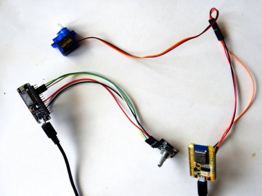
Congratulations! You have completed the project.
Picture 1 shows the connected and powered up project.
If you rotate the Rotary Encoder back and forth, the Servo will move in the same direction, as you can see in the video. If you press the Rotary Encoder shaft down, the Servo will move to neutral center position.
On Picture 2 you can see the complete Visuino diagram for the Rotary Encoder Remote Control module.
On Picture 3 you can see the complete Visuino diagram for the Servo module.
Also attached are the Visuino projects, that I created for this Tutorial. You can download and open them in Visuino: https://www.visuino.com
Credits
Related products


Leave your feedback...