
Esp8266: Dht11 Temperature And Humidity Web Server

About the project
Build and program your own ESP8266 Temperature and Humidity web server - quick and easy!
Items used in this project
Hardware components

Software apps and online services
Story
ESP8266 modules are great low cost stand alone controllers with built in Wi-Fi, and I already made a number of tutorials about them.
DTH11/DTH21/DTH22 and AM2301 are very popular combined low cost Temperature and Humidity Arduino sensors.
In this tutorial I will show you how you can make a Temperature and Humidity Web Server with ESP8266 and DHT11 and connect to it on your existing Wi-Fi network from multiple devices with a web browser.
Step 1: Components

- One NodeMCU ESP8266 board (I used NodeMCU 0.9 version, but any other, or even stand alone ESP-12 or ESP-01 will work)
- One DHT11 Sensor module I got from this cheap 37 sensors set
- 3 Female-Female jumper wires
1 / 4 • Picture 1

Picture 1

Picture 2

Picture 3

Picture 4
- Connect Power (red wire), Ground (black wire), and Data (gray wire) to the DHT11 Module (Picture 1 shows 2 different types of DHT11 sensor modules. As you can see the pins may differ, so connect carefully!)
- Connect the other end of the Ground wire (black) to the Ground pin of the ESP8266 module (Picture 2)
- Connect the other end of the Power wire (red) to the 3.3V Power pin of the ESP8266 module (Picture 2)
- Connect the other end of the Data wire (gray) to the Digital pin 2 of the ESP8266 module (Picture 3)
- Picture 4 shows where are the Ground, 3.3V Power, and Digital 2 pins of the NodeMCU 0.9
1 / 2 • Picture 1

Picture 1

Picture 2
To start programming the Arduino, you will need to have the Arduino IDE installed from here: http://www.arduino.cc.
Please be aware that there are some critical bugs in Arduino IDE 1.6.6.
Make sure that you install 1.6.7 or higher, otherwise this Tutorial will not work!
If you have not done follow the steps in this tutorial to setup the Arduino IDE to program ESP 8266!
The Visuino: https://www.visuino.com also needs to be installed.
- Start Visuino as shown in the first picture
- Click on the "Tools" button on the Arduino component (Picture 1) in Visuino
- When the dialog appears, select "NodeMCU ESP-12" as shown on Picture 2
1 / 4 • Picture 1

Picture 1

Picture 2

Picture 3

Picture 4
First we need to configure the module to connect to existing Access Point and to assign HostName to it so we can discover it on the network.
- In the Object Inspector, expand the “Modules” property, then the “WiFi” sub property
- In the Object Inspector set the value of the "HostName" property to "dht11server" (Picture 1)
- In the Object Inspector, expand the “AccessPoints” sub property of the “WiFi”, and click on the "..." button next to its value (Picture 2)
- In the "AccessPoins" editor, select “WiFi Access Point” in the right view, and then click on the "+" button on the left to add the access point (Picture 2)
- In the Object Inspector, set the value of the "SSID" property to the SSID of your Wi-Fi Hotspot (Access Point) (Picture 4)
- If your Wi-Fi Hotspot (Access Point) requires password, in the Object Inspector, set the password in the value of the "Password" property (Picture 4)
- Close the "AccessPoints" dialogue.
1 / 3 • Picture 1

Picture 1

Picture 2

Picture 3
Next we need to add an TCP/IP Server socket for the communication.
In the Object Inspector, click on the "..." button next to the value of the "Sockets" sub property of the WiFi (Picture 1).
- In the Sockets editor select “TCP/IP Server”, and then click on the "+" button (Picture 2) to add one (Picture 3)
- Close the "Sockets" dialogue
1 / 5 • Picture 1

Picture 1

Picture 2

Picture 3

Picture 4

Picture 5
To control and read the Temperature and Humidity from the DHT11 we need to add component for it in Visuino.
We also need to generate the web page from the data. The page is just an HTML text document, so we can use Formatted Text component to generate it.
- Type "dht" in the Filter box of the Component Toolbox then select the "Humidity and Thermometer DHT11/21/22/AM2301" component (Picture 1), and drop it in the design area
- Type "form" in the Filter box of the Component Toolbox then select the "Formatted Text" component (Picture 2), and drop it in the design area
- Click on the "Tools" button of the FormattedText1 component (Picture 3)
In the Elements editor, select the Analog Element on the right, and click 2 times on the "+" button on the left (Picture 4), to add 2 of them (Picture 5)
- Close the "Elements" editor
1 / 2 • Picture 1

Picture 1

Picture 2
We need to specify the HTML text that will be generated when a web client connects to the server.
We will specify the connection to close after the data i sent, and also will instruct the browser to reconnect (Refresh) after 5 seconds by adding "Refresh: 5" to the document. This way the web page will refresh every 5 seconds.
- In the Design Area, select the FormattedText1 component (Picture 1)
- In the Object Inspector select the "Text" property, and click on the "..." button next to its value (Picture 1)
- In the "Text" editor type (Each quoted string is a new line, as shown on Picture 2 ):
"HTTP/1.1 200 OK" "Content-Type: text/html" "Connection: close" "Refresh: 5" "" "<!DOCTYPE HTML>" "<html>" "<body>" "Temperature: %0" "Humidity: %1" "</body>" "</html>"
EndFragment "Temperature: %0""Humidity: %1" (Picture 2).The %0 will be replaced with the value from AnalogElement1, and %1 will be replaced with the value from AnalogElement2
- Click on the OK button to close the dialog
1 / 3 • Picture 1

Picture 1

Picture 2

Picture 3
- Connect the "Temperature" output pin of the HumidityThermometer1 component to the "In" pin of the AnalogElement1 of the FormattedText1 component (Picture 1)
- Connect the "Humidity" output pin of the HumidityThermometer1 component to the "In" pin of the AnalogElement2 of the FormattedText1 component (Picture 2)
- Connect the "Sensor" pin of the HumidityThermometer1 component to the "Digital" input pin of the "Digital[ 2 ]" channel of the Arduino component (Picture 3)
1 / 3 • Picture 1

Picture 1

Picture 2

Picture 3
We need to send the HTML text every time there is a new connection. To do that we will use Detect Edge component to detect the changing from False to True of the Connected pin of the TCP/IP Server Socket.
- Type "detect" in the Filter box of the Component Toolbox then select the "Detect Edge" component (Picture 1), and drop it in the design area
- Connect the “Connected” pin of the “Modules.WiFi.Sockets.TCPServer1” of the “NodeMCU ESP-12” component, to the “In” pin of the DetectEdge1 component (Picture 2)
- Connect the "Out" pin of the DetectEdge1 component to the "Clock" input pin of the FormattedText1 component (Picture 3)
1 / 4 • Picture 1

Picture 1

Picture 2

Picture 3

Picture 4
- Connect the “Out” pin of the FormattedText1 component to the “In” pin of the "Modules.WiFi.Sockets.TCPServer1” of the “NodeMCU ESP-12” component (Picture 1)
- Type "delay" in the Filter box of the Component Toolbox then select the "Delay" component (Picture 2), and drop it in the design area
- Connect the “Out” pin of the FormattedText1 component to the “In” pin of the Delay1 component (Picture 3)
- Connect the “Out” pin of the Delay1 component to the “Disconnect” input pin of the "Modules.WiFi.Sockets.TCPServer1” of the “NodeMCU ESP-12” component (Picture 4)
The Delay component will disconnect the socket shortly after the text has been sent.
Step 11: Generate, Compile, and Upload the Arduino code
1 / 2 • Picture 1

Picture 1

Picture 2
- In Visuino, Press F9 or click on the button shown on Picture 1 to generate the Arduino code, and open the Arduino IDE
- Connect the NodeMCU module with USB cable to the computer
- Select the board type and serial port as I have shown you in this tutorial
- In the Arduino IDE, click on the Upload button, to compile and upload the code (Picture 2)
1 / 2 • Picture 1

Picture 1

Picture 2
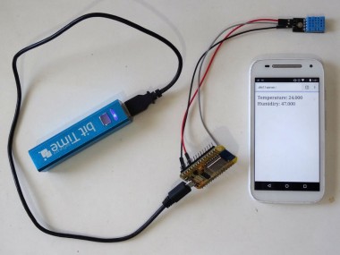
Congratulations! You have made a Wi-Fi Temperature and Humidity Web Server.
On Picture 1 and in the Video you can see the connected and powered up project. I used a small USB Power Bank to power the module.
Make sure in the project on Step 4 you have entered the correct SSID and Password for your Wi-Fi hotspot!
If you open a web browser on your computer or mobile device, and type: dht11server./
And press Enter, you will see the temperature and humidity measured by the module.The reading will refresh every 5 seconds as specified in Step 7 .
Make sure to add the Dot at the end of the name, otherwise Windows will not be able to resolve the domain name!
On Picture 2 you can see the complete Visuino diagram. Also attached is the Visuino project, that I created for this Tutorial. You can download and open it in Visuino.
To run the attached project, you will need to set the SSID and Password for your Wi-Fi Hotspot as shown on Step 4!
Credits
Related products


Leave your feedback...