
Electronic Dice Using Atom Matrix Esp32

Made by Ron / Displays / Games & Gaming / Kids & Family / Lights / Sensors
About the project
In this Tutorial we are going to make an Electronic Dice that will display a different number every time you shake the Atom Matrix ESP32.
Project info
Difficulty: Easy
Platforms: Arduino, Visuino, M5Stack
Estimated time: 1 hour
License: GNU General Public License, version 3 or later (GPL3+)
Items used in this project

Story
The project is based on a built-in accelerometer where we detect the force of the movement.
In this tutorial we will use dots as on the real dice but if you prefer numbers you should check out this tutorial:
Shake the Dice Using Atom Matrix ESP32
Watch the video!
Step 1: What You Will Need1 / 2
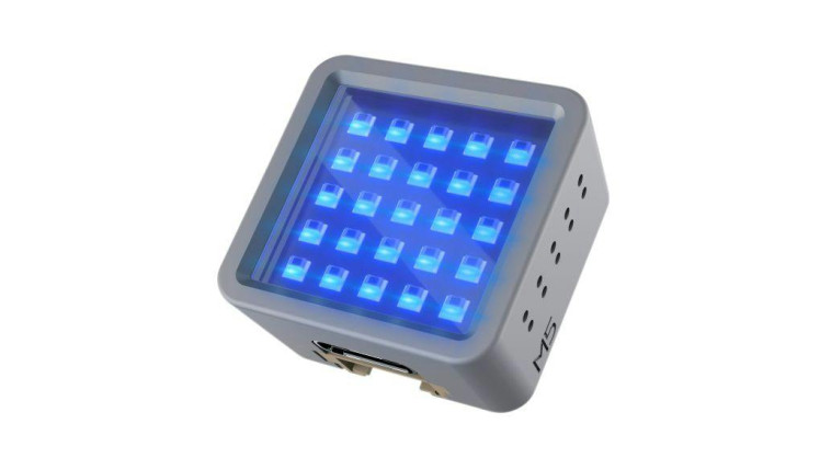
- ATOM Matrix ESP32 More info
- Visuino program: Download Visuino
1 / 2

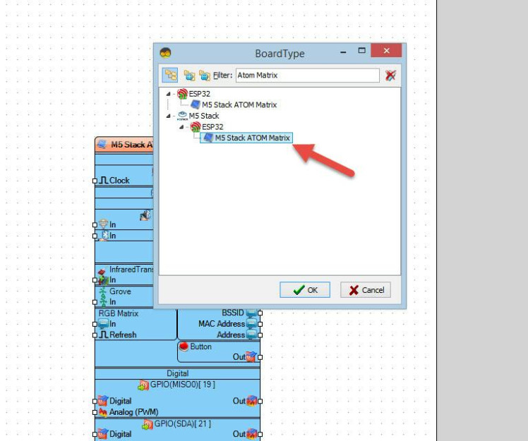
Start Visuino as shown in the first picture Click on the "Tools" button on the Arduino component (Picture 1) in Visuino When the dialog appears, select "Atom Matrix" as shown on Picture 2
Step 3: In Visuino Add Components1 / 8

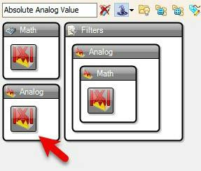
- Add "Absolute Analog Value" component
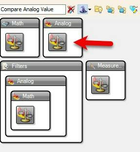
- Add "Compare Analog Value" component
- Add "Timer" component
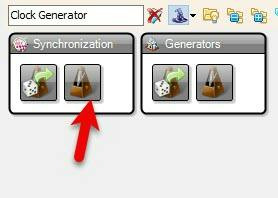
- Add "Clock Generator" component
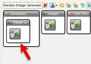
- Add "Random Integer Generator" component
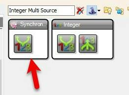
- Add "Integer Multi Source" component
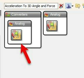
- Add "Acceleration To 3D Angle and Force" component
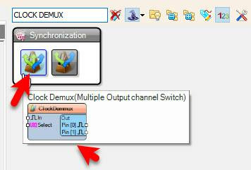
- Add "Clock Demux(Multiple Output channel Switch)" component
1 / 13

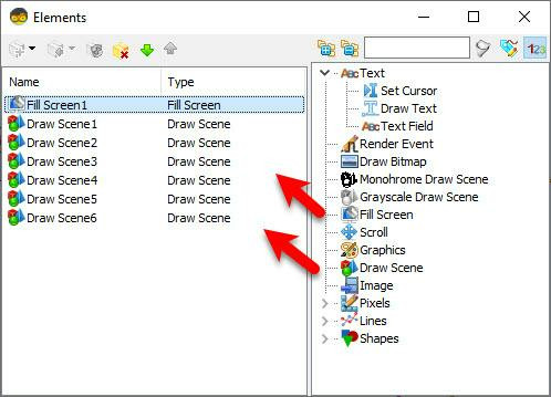
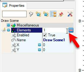

- Select "M5 Stack ATOM Matrix" board and in the properties window expand "Modules">"RGB Matrix">"Elements" and click on the 3 dots button
- In the "Elements" window drag "Fill Screen" to the left side
- In the "Elements" window drag 6X "Draw Scene" to the left side,
For:
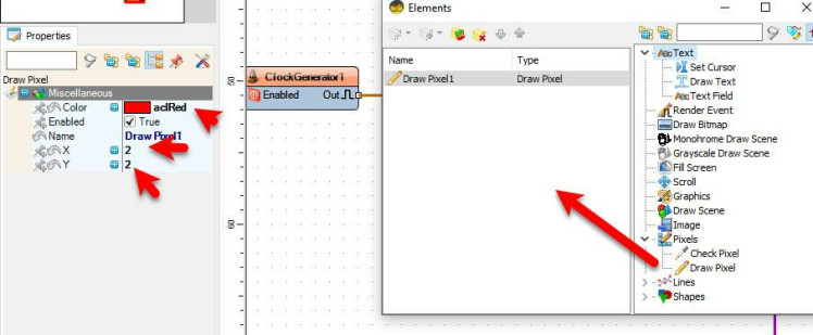
"Draw Scene1" in the properties window select "Elements" and click on the 3 dots button, in the "Elements" window drag "Draw Pixel" to the left side
- and in the properties window set "Color" to aclRed and "X" to 2 and "Y" to 2
- Close the "Elements" window
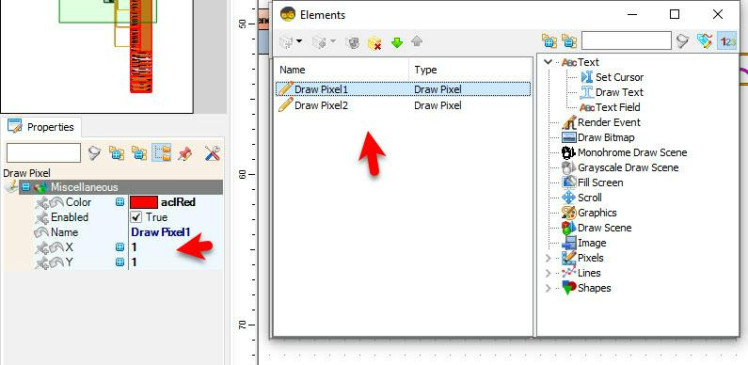
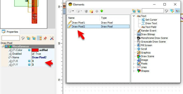
"Draw Scene2" in the properties window select "Elements" and click on the 3 dots button, in the "Elements" window drag "Draw Pixel" to the left side
- and in the properties window set "Color" to aclRed and "X" to 1 and "Y" to 1
drag another "Draw Pixel" to the left side
- and in the properties window set "Color" to aclRed and "X" to 3 and "Y" to 3
- Close the "Elements" window
"Draw Scene3" in the properties window select "Elements" and click on the 3 dots button, in the "Elements" window drag "Draw Pixel" to the left side
- and in the properties window set "Color" to aclRed and "X" to 1 and "Y" to 3
drag another "Draw Pixel" to the left side
- and in the properties window set "Color" to aclRed and "X" to 2 and "Y" to 2
drag another "Draw Pixel" to the left side
- and in the properties window set "Color" to aclRed and "X" to 3 and "Y" to 2
- Close the "Elements" window
"Draw Scene4" in the properties window select "Elements" and click on the 3 dots button, in the "Elements" window drag "Draw Pixel" to the left side
- and in the properties window set "Color" to aclRed and "X" to 1 and "Y" to 1
drag another "Draw Pixel" to the left side
- and in the properties window set "Color" to aclRed and "X" to 1 and "Y" to 3
drag another "Draw Pixel" to the left side
- and in the properties window set "Color" to aclRed and "X" to 3 and "Y" to 1
drag another "Draw Pixel" to the left side
- and in the properties window set "Color" to aclRed and "X" to 3 and "Y" to 3
- Close the "Elements" window
"Draw Scene5" in the properties window select "Elements" and click on the 3 dots button, in the "Elements" window drag "Draw Pixel" to the left side
- and in the properties window set "Color" to aclRed and "X" to 1 and "Y" to 1
drag another "Draw Pixel" to the left side
- and in the properties window set "Color" to aclRed and "X" to 1 and "Y" to 3
drag another "Draw Pixel" to the left side
- and in the properties window set "Color" to aclRed and "X" to 3 and "Y" to 1
drag another "Draw Pixel" to the left side
- and in the properties window set "Color" to aclRed and "X" to 3 and "Y" to 3
drag another "Draw Pixel" to the left side
- and in the properties window set "Color" to aclRed and "X" to 2 and "Y" to 2
- Close the "Elements" window
"Draw Scene6" in the properties window select "Elements" and click on the 3 dots button, in the "Elements" window drag "Draw Pixel" to the left side
- and in the properties window set "Color" to aclRed and "X" to 1 and "Y" to 1
drag another "Draw Pixel" to the left side
- and in the properties window set "Color" to aclRed and "X" to 1 and "Y" to 3
drag another "Draw Pixel" to the left side
- and in the properties window set "Color" to aclRed and "X" to 3 and "Y" to 1
drag another "Draw Pixel" to the left side
- and in the properties window set "Color" to aclRed and "X" to 3 and "Y" to 3
drag another "Draw Pixel" to the left side
- and in the properties window set "Color" to aclRed and "X" to 1 and "Y" to 2
drag another "Draw Pixel" to the left side
- and in the properties window set "Color" to aclRed and "X" to 3 and "Y" to 2
- Close both "Elements" window
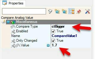
- Select "CompareValue1" and in the properties window set "Compare Type" to ctBigger and "Value" to 1.7
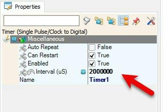
- Select "Timer1" and in the properties window set "Interval (uS)" to 2000000
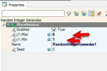
- Select "RandomIntegerGenerator1" and in the properties window set "Max" to 6 and "Min" to 1
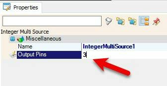
- Select "IntegerMultiSource1" and in the properties window set "Output Pins" to 3
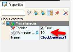
- Select "ClockGenerator1" and in the properties window set "Frequency" to 10
- Select "ClockGenerator1" and in the properties window select "Enabled" & click on the pin Icon and select "Boolean SinkPin"
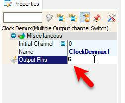
- Select "ClockDemmux1" and in the properties window set "Output Pins" to 6
1 / 5
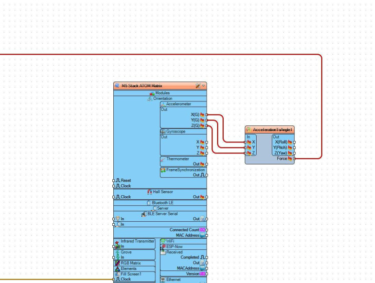
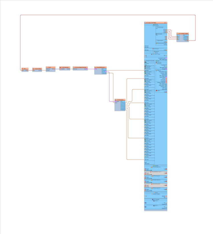
- Connect M5 Stack ATOM Matrix > Accelerometer pin [X] to "AccelerationToAngle1" pin [X]
- Connect M5 Stack ATOM Matrix > Accelerometer pin [Y] to "AccelerationToAngle1" pin [Y]
- Connect M5 Stack ATOM Matrix > Accelerometer pin [Z] to "AccelerationToAngle1" pin [Z]
- Connect "AccelerationToAngle1" pin [Force] to Abs1" pin [In]
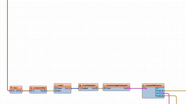
- Connect "Abs1" pin [Out] to CompareValue1" pin [In]
- Connect "CompareValue1" pin [Out] to "Timer1" pin [Start]
- Connect "Timer1" pin [Out] to "ClockGenerator1" pin [Enabled]
- Connect "ClockGenerator1" pin [Out] to "RandomIntegerGenerator1" pin [In]
- Connect "RandomIntegerGenerator1" pin [Out] to "IntegerMultiSource1" pin [In]
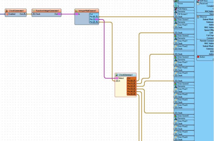
- Connect "IntegerMultiSource1" pin [0] to "M5 Stack ATOM Matrix" > "Fill Screen1" pin [Clock]
- Connect "IntegerMultiSource1" pin [1] to "ClockDemmux1" pin [Select]
- Connect "IntegerMultiSource1" pin [2] to "ClockDemmux1" pin [In]
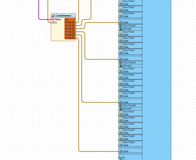
- Connect "ClockDemmux1" pin [0] to "M5 Stack ATOM Matrix" > "Draw Scene1" pin [Clock]
- Connect "ClockDemmux1" pin [1] to "M5 Stack ATOM Matrix" > "Draw Scene2" pin [Clock]
- Connect "ClockDemmux1" pin [2] to "M5 Stack ATOM Matrix" > "Draw Scene3" pin [Clock]
- Connect "ClockDemmux1" pin [3] to "M5 Stack ATOM Matrix" > "Draw Scene4" pin [Clock]
- Connect "ClockDemmux1" pin [4] to "M5 Stack ATOM Matrix" > "Draw Scene5" pin [Clock]
- Connect "ClockDemmux1" pin [5] to "M5 Stack ATOM Matrix" > "Draw Scene6" pin [Clock]
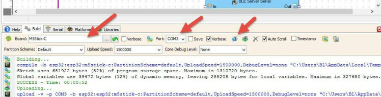
In Visuino, at the bottom click on the "Build" Tab, make sure the correct port is selected, then click on the "Compile/Build and Upload" button.
Step 7: PlayIf you power the ATOM Matrix module and shake it the Display will start to show a random dice number from 1 to 6.
Congratulations! You have completed your project with Visuino. Also attached is the Visuino project, that I created for this tutorial, you can download it and open it in Visuino: https://www.visuino.eu
Schematics, diagrams and documents
Code
Credits
Related products


Leave your feedback...