
Easy And Affordable Track Timing System

Made by collin-wentzien / 3D Printing / Clocks / Displays / Fitness / Sensors
About the project
An affordable and automatic system letting athletes time themselves or their peers quickly and easily.
Project info
Difficulty: Moderate
Platforms: Adafruit, Arduino, SparkFun
Estimated time: 5 days
License: GNU General Public License, version 3 or later (GPL3+)
Items used in this project
Hardware components

View all
Hand tools and fabrication machines
Story
Intro
Hello everyone! Because of my upcoming track and field season at school, I decided to build a timing system to measure my time and others' time when running. The idea with the track timing system is simple. There are two modules: one sitting at the start of the track, and one at the end. With a user-selected delay, the start module plays a start tone and starts a stopwatch. When an athlete crosses the finish line, a light beam is crossed, and the finish module sends a signal to the start module to stop the timer. The athlete’s time is then displayed on the screen, thus acting as an automatic stopwatch. It’s great for timing by yourself, or timing an entire team.
Video
Watch this video if you want to see exactly how the track timer works. If you're not too interested in how I built it, skip to the last few minutes to see me using it on the track!
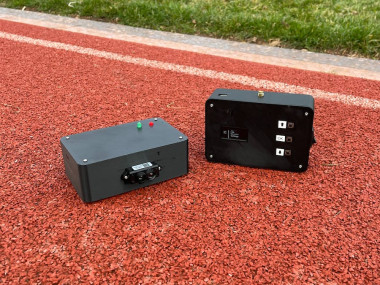
The System Itself
The start module is the control center of the system. It has a small OLED screen and three buttons for a simple menu system. The display allows you to select which mode you want to use, along with other settings that are useful. I'll go over these soon. There is a power switch on the right side, along with a battery cover and speaker grill on the bottom of the device. On the far side, there is also the antenna and a USB port, allowing easy software updates without having to disassemble the entire device. The USB port also allows you to connect the track timer to a computer and write times directly to the computer.
The finish module is even simpler. It too has a power button on the side along with a USB port, an antenna on the back, and a battery cover on the bottom. The top has two LEDs, the red one indicating power, and the green one indicating that the system is ready. However, if you move your attention over to the far side of the module, you’ll notice a camera-like sensor. Now this isn’t actually a camera; instead it’s a LIDAR sensor, which stands for Light Detection and Ranging. Like the name suggests, this sensor detects the range of an object by using light. It’s the same technology that some self-driving cars use!
The LIDAR Sensor
This sensor is actually incredible, as not only can it detect when someone crosses it, but it can detect how far away the person is from the sensor. This is helpful, as it allows the system to differ between people in different lanes. For example, if I was running in lane one and my friend was running in lane two, I wouldn't want him to run by the sensor in lane two and accidentally stop the timer. The system would then print his time instead of mine, which I don't want. So, by telling the system that I am in lane one, the timer can ignore people farther than about half a meter, and only stop if I cross the line.
That’s how detection works on my system!
Timing Modes
Before I go over the parts and other “nerdy” stuff, I’m going to explain the menu on the system. Let’s go back to the start module. On the home screen, there are four options: sprint, lap, counter, and settings. Sprint is for timing a singular person, as it stops the timer once the light beam is crossed. Lap mode is similar, however instead of stopping when the beam is crossed, it stops after the fourth cross, giving you the average for all of your laps along with individual lap times and the entire time put together. Counter mode is made for running in groups. It shows the current time, the time of the last person who crossed the finish module, the lane that is being measured, and the number of runners that have crossed the finish module.
Now, for both sprint and lap mode, there are two options before going into the selected mode. The first is automatic mode, which plays a ready tone, then a set tone, and finally a start tone. The tones have a randomized delay, making it good for practicing starts. The other option is manual mode, which plays a tone when the OK button is pressed. Counter mode only has manual mode, as it is meant for a coach or other person to hold and operate.
Back to the menu system. The final option here is settings. There are three settings that you can customize. The first one, distance, allows you to choose which lane you want to detect. The second option allows you to enable or disable the speaker on the start module. This is useful for coaches who want to call start by themselves, or athletes who want to be quieter. The third and final option calibrates the sensor to the ambient light, along with ignoring any background objects that may be present when calibration begins.
Parts
The parts for this project come out to around ninety dollars, about half of that being for the LIDAR module which is just under forty dollars. However, for a system like this, ninety dollars is miles cheaper than other systems. Here’s the part list. To power the system, I used an Arduino NANO and an Arduino UNO, however two Arduino NANOs will work just fine. To play the start tone, I used a four ohm, three watt speaker, along with an LM386 amplifier to increase the volume of the tones. For the display, I of course opted for a 1.3 inch OLED screen. To send and receive data, I used two nRF24L01 modules with antenna, as they have incredible range and very low latency. To measure when someone crosses the finish line, I used the TFmini-s LIDAR sensor that I found off of Amazon. The reason I used this sensor was because of its twelve meter range, meaning it can cover an entire track. It’s also very reliable, and I have yet to encounter any problems with it. Everything is powered by two nine-volt batteries, one in each module. And besides a few pushbuttons, toggle switches, LEDs, and 3D printed parts, that's it!
Links
YouTube - www.youtube.com/c/CollinWentzien
Instagram - @collin.wentzien
Schematics, diagrams and documents
CAD, enclosures and custom parts
Code
Credits
Related products


Leave your feedback...