

Diy Motion Triggered Halloween Prop Using Arduino/digispark

Made by jithin / Kids & Family / Lights / Voice
About the project
Here, you’ll see how to build a cheap and easy digipack-based system that can detect human motion and set off our Halloween decorations.
Project info
Difficulty: Moderate
Platforms: Arduino, Digispark, PCBWay
Estimated time: 1 hour
License: Apache License 2.0 (Apache-2.0)
Items used in this project

Story
Having Halloween decorations that come to life is absolutely fun. Unfortunately, there are significant constraints on what you can accomplish using store-bought props.
Usually, each prop has its own switch or trigger to turn it on, which is a major drawback. Usually, these triggers, whether it is manual or sensor-driven aren’t that durable and it might not work timely. There is no point if the skeleton jumps out of the box after everybody is gone right?
In this video, you’ll see how to build a cheap and easy digipack-based system that can detect human motion and set off our Halloween decorations.
CircuitNow, lets me show you the circuit first!
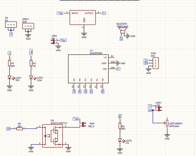
The input power is connected to a 7805 regulator. 7805 is a 5V regulator which will convert an input voltage of 7- 32V to a steady 5V DC supply. So, you can connect an input voltage of anywhere between 7V to 32 to this circuit. For this circuit, I prefer a 9V DC Adapter. There are indicator LEDs across various points for easy troubleshooting.
This is where we connect our digispark.Digispark is a new lightweight microcontroller development board. Digispark comes with 6 GPIO pins, I2C and SPI serial communication, and a USB interface.
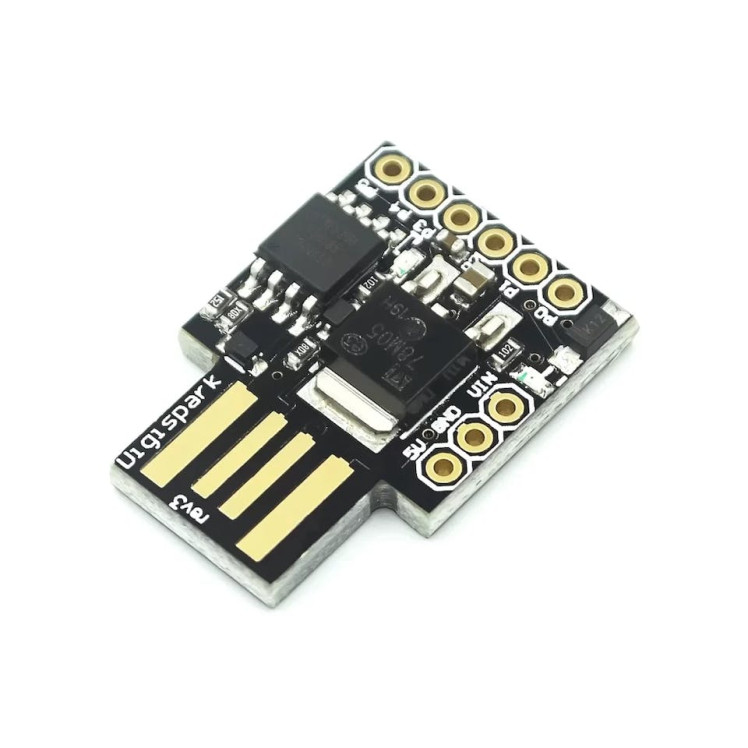
It also has 3 PWM pins, which can control l293d motor drivers or servo motors. we can use Arduino IDE to program digispark but the way we upload the program is a little bit different than usual Arduino. I have explained how it is done in one of the previous videos so you can check that out if needed.
PIR Sensor
This is the sensor that will be triggering our action.
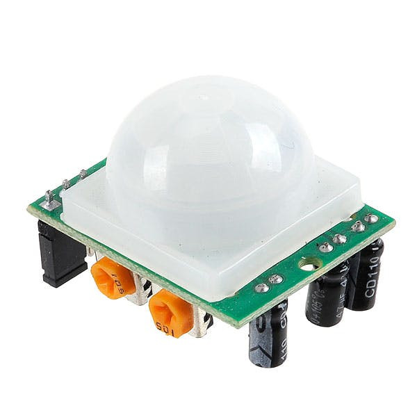
A PIR sensor is a tiny circuit that can detect human beings moving around in front of it within a range of range is between 4 Meters and 13 Meters.
There are mainly 3 pins to PIR Sensor –
VCC – Where we connect 5 V Power Supply
Out – Output Voltage (5V when it detects human IR Signature)
GND – Where we connect -ve Terminal
The PIR is connected to pin P0 of Digispark, which acts as the trigger, and pin P3 is connected to the relay, which will be connected to the actuator or circuit that does the output operation. Here, you will also see a buzzer connected to Pin P2 and an LDR connected to the Analog pin of Digispark if you want to play with lights as well. Also, you will see a potentiometer with which we can adjust the sensitivity of the LDR.
Basically, that’s all I needed for this project. If you are planning on making it, make sure you try it out on a breadboard and once you get the output you can use it as such or create your own PCB.
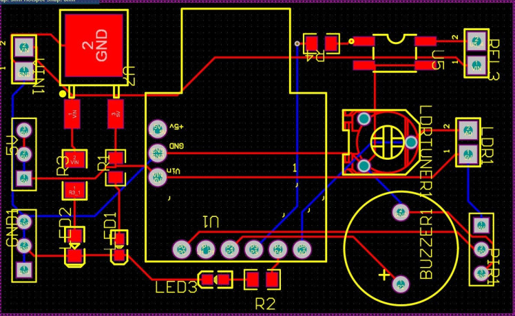
I personally like PCBs. PCBs are neat and help to get rid of all nasty wires hanging around. And it’s cool to make your own PCBs for your project right? Once the circuit was finished and tested, I designed a compact PCB using Altium, where I can fix all the components neatly. Here you can see routing is on both sides of the board which means it is a dual-layer PCB.
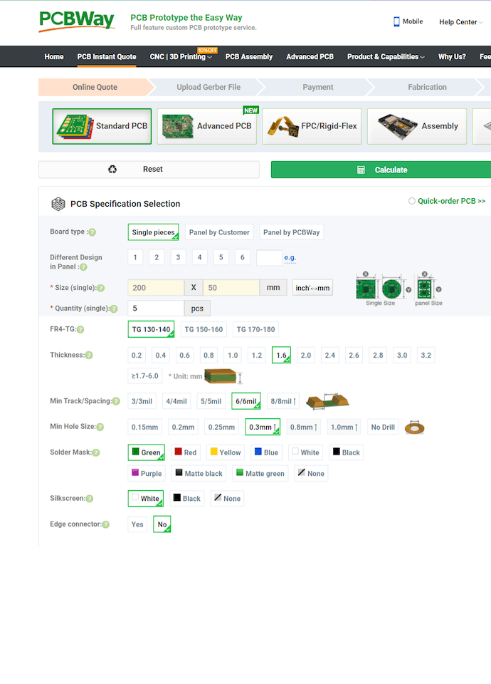
Getting PCB Done from PCBWayI ordered my PCB from PCBWay. PCBWay Is a PCB manufacturer specializing in PCB prototyping, low-volume production, and neat and tidy PCB Assembly. To order your PCB from PCB way, Go to the PCBWay website and fill in the basic board details in the instant order form.

And in the next screen, you can completely customize your PCB. You can change the thickness, change the solder mask color as well as the silkscreen color, materials used, you can customize it in every way possible. Corresponding prices will be updated here in real-time. In PCBWay, you can even manufacture your PCBs with TG 150-160 for the same prices as that of TG 130-140 which means your PCB will be able to operate at high temperatures without any damage.
In the next screen, you should be able to upload your Gerber file and submit it for review. Once the review is completed, all that is left is to add to the cart, make the payment, and wait for your PCBs to arrive.
Once you get all the components and the PCB, it’s time for you to solder them together. Solder all the components onto the board and make sure to check the polarity of the components. After soldering the PCB looks like this.
CodingWe can now upload our code to Digispark. If you dont know how to set up Digispark, check out the video attached.
void setup()
{
pinMode(0, INPUT);
pinMode(4, OUTPUT);//LED
pinMode(2, OUTPUT);//buzzer
pinMode(3, OUTPUT);//relay
pinMode(1, OUTPUT);//inbuild LED
}

void loop()
{

int pir=digitalRead(0);
if(pir==1)
{
digitalWrite(4, HIGH);
//digitalWrite(2, HIGH); //Uncomment If Buzzer is Needed
digitalWrite(3, HIGH);
digitalWrite(1, HIGH);
delay(100);
digitalWrite(6, LOW);
//digitalWrite(2, LOW);//Uncomment If Buzzer is Needed
digitalWrite(3, LOW);
digitalWrite(1, LOW);
}

else
{
digitalWrite(6, LOW);
digitalWrite(2, LOW);
digitalWrite(3, LOW);
digitalWrite(1, LOW);
delay(1000);
}
}
Basically, what the code does is, it will read the value of Pin 0 which is connected to the output of the PIR sensor. If the PIR sensor is sensing a movement or a person, it will turn the output from 0 to 1. If the value of the PIR input is 1, then it will turn on the relay. If not, it will not. When the relay is turned on, whatever is connected to that circuit will also turn on!
Once it is done, connect the power adapter and you will see LED1 will glow up. This means it is working. Now all you have to do is replace the switch of your Halloween prop with the output of the relay.
TestingIn my case, I didn’t remove the button here, instead, I opened the bottom part of the prop, and soldered the relay output to the pins where the switch was connected. Another thing to keep in mind is that you have to make sure that the voltage is almost as same as the potential difference between the pins of the switch or the sensor otherwise, you might burn the circuit.

Once that is done, turn on the circuit, turn off the light, and place the whole setup in such a way that the PIR sensor faces the way, let people might walk in.
Have fun guys!
Credits
Related products


Leave your feedback...