
Diy Electronic Horn For A Bicycle Or Car

Made by ElectroGuruji / Automotive / Bikes / Music / Notifications / Vehicles
About the project
The LM555 generates an electronic horn signal which is amplified by an LM386. The tone and gain of the horn can be easily varied. The horn can be used in a car, scooter, cycle, and motorbike.
Project info
Items used in this project

Story
The LM555 generates an electronic horn signal which is amplified by an LM386. The tone and gain of the horn can be easily varied. The horn can be used in a car, scooter, cycle, and motorbike.
Don't forget to Subscribe for more projects: YouTube
Step 1: Parts & Tools

Electronic Components:
- 1x IC 555 AliExpress
- 1x IC LM386 AliExpress
- 2x IC Holder AliExpress
- 1x 10Ω Resistor AliExpress
- 1x 1KΩ Resistor AliExpress
- 1x 2KΩ Resistor AliExpress
- 3x 10KΩ Potentiometer AliExpress
- 1x Tactile Momentary Push Buttons AliExpress
- 1x 5mm LED AliExpress
- 1x 0.1uF Capacitor AliExpress
- 1x 10uF Capacitor AliExpress
- 1x 100uF Capacitor AliExpress
- 1x 220uF Capacitor AliExpress
- 1x 10nF Capacitor AliExpress
- 1x 47nF Capacitor AliExpress
- 1x 100nF Capacitor AliExpress
- 1x Speaker AliExpress
- 1x 9V Battery Holder AliExpress
- 1x 9V Battery AliExpress
- 1x PCB AliExpress
Tools:
- Soldering Iron AliExpress
- Soldering Wire AliExpress
- Mini PCB Hand Drill + Bits AliExpress
You can also Buy the PCB
Step 2: LM555 Explained


The 555 is a highly stable device for generating accurate time delays or oscillation. Additional terminals are provided for triggering or resetting if desired. For stable operation as an oscillator, the free running frequency and duty cycle are accurately controlled with two external resistors and one capacitor. The circuit may be triggered and reset on falling waveforms, and the output circuit can source or sink up to 200mA or drive TTL circuits.
Step 3: LM386 Explained


The LM386 is a power amplifier designed for use in low voltage consumer applications. The gain is internally set to 20 to keep external part count low, but the addition of an external resistor and capacitor between pins 1 and 8 will increase the gain to any value from 20 to 200.
The inputs are ground referenced while the output automatically biases to one-half the supply voltage.
Step 4: Working & Calculations


An LM555 is used to generate the horn signal. The LM555 is connected such that it will trigger itself and free run as an astable multivibrator. The external capacitor charges through Ra+Rb and discharges through Rb. Thus the duty cycle may be precisely set by the ratio of these two resistors.
In this mode of operation, the capacitor charges and discharges between 1/3 VCC and 2/3 VCC. Hence the charge and discharge times, and therefore the frequency is independent of the supply voltage.
A momentary switch acts as an input trigger that enables the astable multivibrator to generate a signal of variable frequency. This signal is then sent to an amplification unit before it is played through a speaker. The frequency and volume of the horn sound can be varied as shown.
Step 5: Circuit Schematic

A potentiometer R3 (Rb) is varied in order to change the frequency of the signal generated by the LM555. The signal is then passed to the LM386 for amplification.
The input signal is passed through another potentiometer R4 before it reaches the LM386. This pot is used to change the amplitude (volume) of the input signal before amplification.
The LM386 has a 10uF capacitor and 10K potentiometer R5 connected between pins 1 and 8. By varying this pot, we can change the gain of the amplifier and thus the volume of the amplified signal.
A push button/ momentary switch is used to turn on the circuit thereby producing a loud horn sound.
Capacitors connected across the supply terminals are used to minimize any noise signals.
Eagle Schematic: GitHub
Step 6: PCB Fabrication


I fabricated the board using the Iron Method.
I drilled four mounting holes in each corner with a diameter of 3mm.
The PCB size is 7.5cm X 5cm .
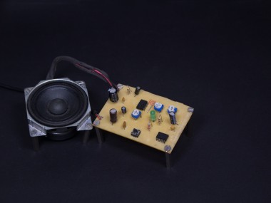
Step 7: Circuit Assembly


Place and solder all the components onto the PCB. Double check components with polarities. Lastly, solder the Power adapter and speaker to the PCB.
Step 8: Adjust the Tone & Volume


You can vary the tone and volume of the horn by changing the position of the potentiometers using a screwdriver.
Potentiometer R3 is varied to change the tone(frequency) of the horn. Potentiometer R4 is used to change the volume(amplifier gain) of the horn.
Step 9: Support These Projects

- YouTube: Electro Guruji
- Instagram: @electroguruji
- Twitter: ElectroGuruji
- Facebook: Electro Guruji
Are you an engineer or hobbyist who has a great idea for a new feature in this project? Maybe you have a good idea for a bug fix? Feel free to grab the schematics from GitHub and tinker with it.
If you have any questions/doubts related to this project, leave them in the comments section and I will try my best to answer them.
Schematics, diagrams and documents
Code
Credits
Related products


Leave your feedback...