
Diy Basketball Scoreboard

Made by collin-wentzien / 3D Printing / Clocks / Displays / Fitness / Lights
About the project
A professional-level scoreboard featuring a wireless controller, bright lights, and a loud horn.
Project info
Difficulty: Difficult
Platforms: Adafruit, Arduino, SparkFun
Estimated time: 3 weeks
License: GNU General Public License, version 3 or later (GPL3+)
Items used in this project
Hardware components

View all
Hand tools and fabrication machines
Story
What’s up everyone!
My name is Collin and I am a 16 year old maker. Today I’m going to show you how I built a scoreboard back in 2019 (when I was 13 years old); featuring a wireless controller, bright lights, and a super loud horn. I'll also show you all the parts needed and briefly explain how I built it, in case you want to make one yourself.
Let's get started!
Video
Background
When I was in elementary school, I ran the scoreboard for local recreational basketball games. I always enjoyed seeing the digits change, and especially liked the horn, as every little kid does.
In 7th grade, I got the idea to make my own scoreboard. I had already owned a scoreboard, but it didn’t have many of the more professional features that expensive scoreboards had, such as a wireless controller, bar-style digits, and a horn. So, like every half-insane maker, I decided to make my own.
The Scoreboard

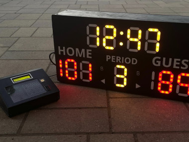
Scoreboard powered on
Here’s the scoreboard. It displays time, score, period, possession, and bonus. The scoreboard turns on by flipping a switch on its side. Once the scoreboard is on, you just flip a switch on the controller to power it on as well.
And with both devices on, the scoreboard lights up!
The Controller

Scoreboard controller powered on
Here are some of the scoreboard's basic functions. To start the clock, you flip the switch on the bottom right. Up to start, down to stop. You can also set the time to whatever you want by pressing “Set, ” then “Time, ” and then typing in the time you want with the keypad and saving it by pressing "Enter."
Adding score is very easy, too. On the controller, home is in green and guest is in red. You can add score in increments of 1, 2, and 3, and also subtract score. The buttons for possession and bonus are here as well.
You can also set score by pressing “Set, ” and then selecting either home score or guest score. You then just type in the score you want and press “Enter” to set it.
Changing period is very easy as well, as you just press the "Period +1" button to increment the period. Once it reaches 9, it resets back to 0.
And finally, my favorite button: the horn.
Inside
Here’s a quick view inside the scoreboard and controller.
")
Inside of the scoreboard. Ignore the messy wiring ;)
This is the inside of the scoreboard. To the right, you can see the power supply and wall socket. Right above it is the Arduino UNO, along with the wireless module. This attaches to the antenna connected to the back of the scoreboard like so. Over to the middle is the relay, and close by is the horn itself. To power everything and make it easier to swap out high voltage components, I added a power bank. And finally, you can see all the lights on the front of the scoreboard.

Inside of controller
Onto the controller. Inside the base, there is a power circuit to power the Arduino MEGA, as well as another antenna to connect to the scoreboard. The front of the controller contains the more complex electronics. Here you can see the keypad, the screen, wireless module, switch, and of course, the Arduino MEGA.
Ok, on to the build.
Building
The first step to this project was planning it out. Since it was a considerable investment, around $400, I had to ensure that the money I spent was being properly used and not being wasted. Once everything had been planned out, I then began designing it in Adobe Illustrator. The scoreboard would be 2 feet wide by 1 foot tall, making it small enough to carry around. It would also be made out of wood, which would make it lighter and easier to work on compared to plastic or metal.
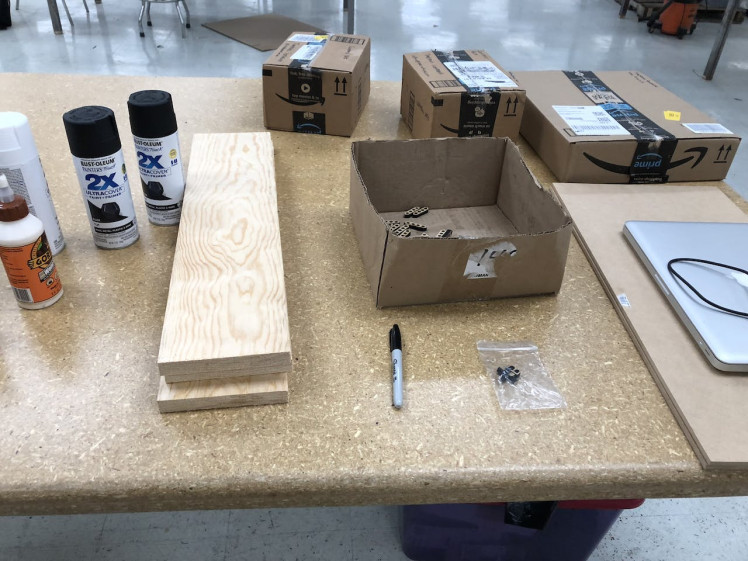
Next, I ordered all the parts off of Amazon. I bought an Arduino UNO to be the brains of the scoreboard. I also bought hundreds of red and yellow LEDs to make the digits. I ended up changing these LEDs out for these WS2812B addressable LEDs for reasons I’ll explain later. To power the LEDs, I bought a 5 volt, 5 amp power supply, as the Arduino would not be able to supply enough power to the LEDs. To communicate between the scoreboard and controller, I used two nRF24L01 modules. And finally, I bought a Federal Signal 350 horn, the same one used in professional scoreboards, along with a relay to switch it on and off.
The scoreboard front was made from ¼ inch MDF, again being 2 feet wide by 1 foot tall. The sides were made from ½ inch wood, being six inches wide to allow the horn to sit. A cutout was made on one side so I could install a power socket, as the horn required 120 volts AC to work. This power socket also ran the power supply that ran the Arduino and lights.
On to the controller. The controller uses an Arduino MEGA and an nRF24L01 module to operate and communicate with the scoreboard. To receive inputs, I made a 7 by 4 button keypad, which the user would use to control the scoreboard. To display info to the user, I added a 16x2 character LCD. And besides an extra button for the horn and two switches for starting the clock and powering the controller, that’s it.
With the parts all bought, it was time to actually build the scoreboard. So, I took a trip down to TheShop.build to laser cut all the parts.
So, I went in with a bunch of wood and glue, and came out with something that slightly resembled a scoreboard? Anyways, I laser cut the front of the scoreboard out, along with diffusers made from clear acrylic. I wanted these diffusers, which the light would shine through, to have a frosted appearance. That way, when the light shone through, the whole digit would illuminate, instead of just the individual lights. It looks way cooler in my opinion and I really wanted to achieve this look. So, with the help of one of the employees there, I used a sandblaster for the first time and gave the acrylic a really cool appearance. Unfortunately, the acrylic didn’t work as well as I hoped, and I again changed plans later on.
I also cut out the controller out of ¼ inch wood.
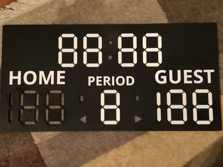
The final thing I did was cut out the words, “Home, ” “Guest, ” and “Period” from white sticker vinyl. These would act as team names on the scoreboard.
Back at home, I painted the scoreboard and added the vinyl stickers. Here’s how it looked. I also started assembling all the LED segments.
Problems! (so fun)
Here’s where I ran into some issues. My original plan used around 312 LEDs, each which I would have to individually solder together. That’s a lot. I also had to wire up these LEDs to the Arduino, and while there are many ways to control multiple LEDs from just a couple pins, it would be a lot of work and a lot of soldering. So, I modified my original plan and bought a set of WS2812B addressable LEDs. These LEDs were amazing, as not only were they super bright, but I could control all of them from 3 pins. Perfect! With these new lights, I then began assembling all the digits needed. These still took a while to solder, but in hindsight, were way quicker to make than the individual LEDs would have been. Did I mention that they’re RGB? Yep, I can change the digits to whatever color I want. It’s pretty cool.
Here’s when I ran into my second roadblock. The acrylic pieces that I cut weren’t that effective, and on top of that, they were slightly too loose in the holes I cut out for them. So again, I changed my plan and decided to 3D print the diffusers.
I went through multiple design iterations before I finally decided on some that seemed to work well enough. I had to find a balance between making the digits bright and diffusing the lights, which in the end I think I was able to do. Here’s how the board looked with a few diffusers in.
After a week or two of soldering digits, I finally finished them all. Almost 500 wires had to be cut, stripped, and soldered! I then glued the lights in, and tested them out.
Almost forgot to mention; I switched out the 5 volt 5 amp power supply for a 5 volt 20 amp power supply, as at full brightness, the calculated power draw of the LEDs was around 8.4 amps.
Anyways, the LEDs worked… sort of. For some reason they would flicker sporadicly and often not work at all. I therefore decided to take a small break.
Finishing the Project
In the meantime, I worked on the controller. The most challenging part was by far the code, as the scoreboard is actually completely run by the controller. Let me explain.
This type of communication is known as leader and follower. In this scenario, the controller acts as the leader, and the scoreboard acts as the follower. The controller sends all instructions to the scoreboard, and the scoreboard receives all the instructions and processes them. The scoreboard never sends instructions to the controller. This means that the controller is the device that does all the hard work, like keeping time, score, etc. The scoreboard only displays this data that it receives from the controller.
With a few bugs here and there, the code was done and the controller was almost completed.
Back to the scoreboard. Eventually, after a few months’ break, I figured out the issue. Since I was using an external power supply, separate from the Arduino, I had to add a common ground between the power supply and the Arduino. One wire caused me months of delay. One wire!
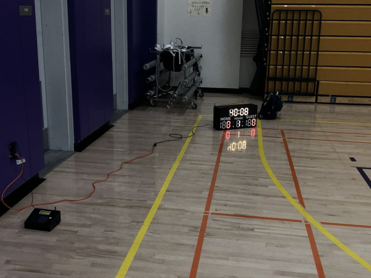
With that issue fixed, however, the scoreboard was practically done. With a few tweaks to the code, the scoreboard and controller were finished in November of 2019!
Thank you!
That’s pretty much it for this project. As usual, all code, files, schematics, and images are linked here or on my GitHub. Please let me know if you have any questions or suggestions, as I would love to hear them.
Links
YouTube - www.youtube.com/c/CollinWentzien
Instagram - @collin.wentzien
Schematics, diagrams and documents
CAD, enclosures and custom parts
Code
Credits
Related products


Leave your feedback...