
Digital Back

Made by amc / Environmental Sensing / Health / Home Automation / Sensors / IoT
About the project
The main issue this project will try to address is to improve our sitting habits. The Idea behind the project is to equip the back of your chair with a number of range sensors and measure your sitting position. A user will be notified by a small vibration motor about invalid sitting postion.
Project info
Difficulty: Difficult
Platforms: NXP
Estimated time: 1 week
License: GNU General Public License, version 3 or later (GPL3+)
Items used in this project
Hardware components

View all
Hand tools and fabrication machines
View all
Story
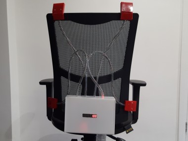
Overview
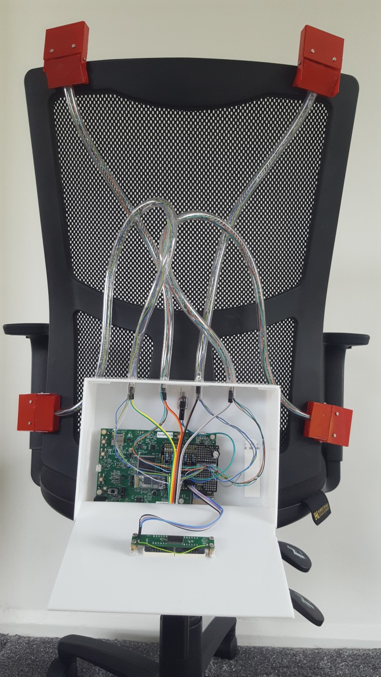
Working from home has become a new norm. Many companies shifted their open plan offices to remote work or a mixed environment when we spend only a few days in the office. Working from home has a number of benefits but also faces a number of challenges. The main issue this project will try to address is the improvement of our sitting habits. Working from home means long hours in front of your computer. Maintaining a good posture and keeping frequent breaks is very important for our wellbeing. The idea behind the project is to equip the back of your chair with a number of range sensors and measure your sitting position (distance from the back of your chair to your back). Following behaviours could be addressed - Slouching in a chair (sensor on the bottom of your chair back) - Sitting with your weight more on one side (different distance from two sensors on top of the chair back) - Wrong elbows position - Sitting for a very long time without breaks - etc. A user will be notified by a small vibration motor about an incorrect sitting position
Architecture
We will have to address 3 different communication mechanisms:
- UART
- SPI
- direct GPIO
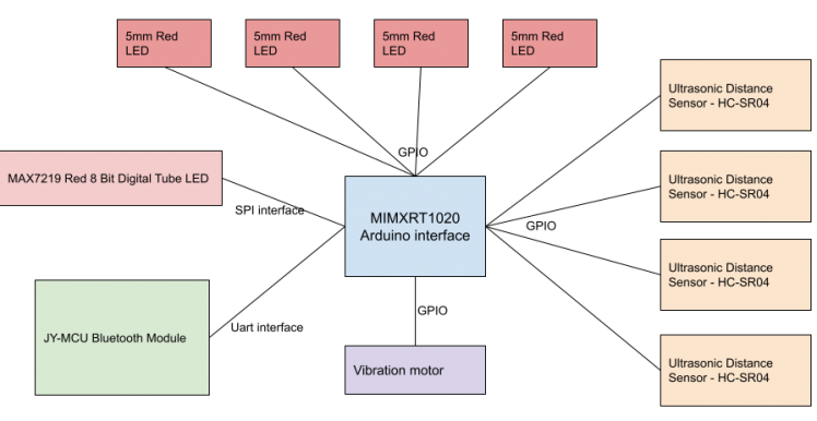
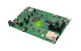
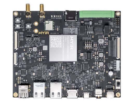
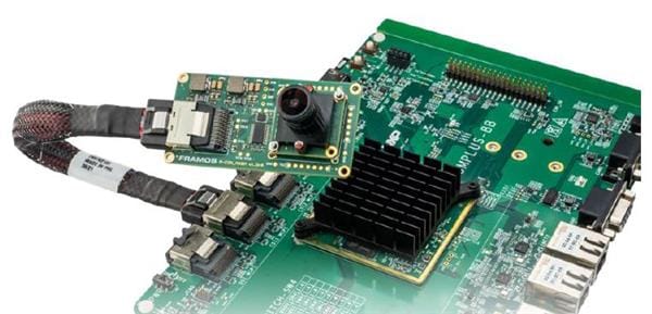
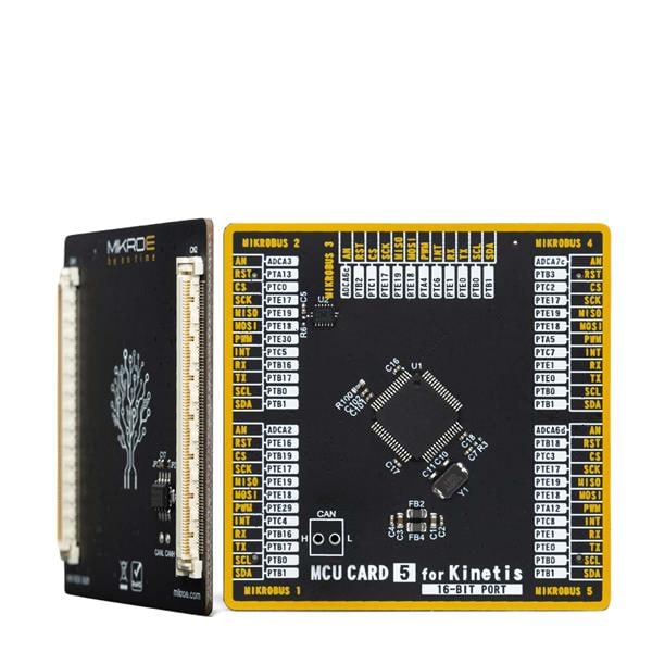
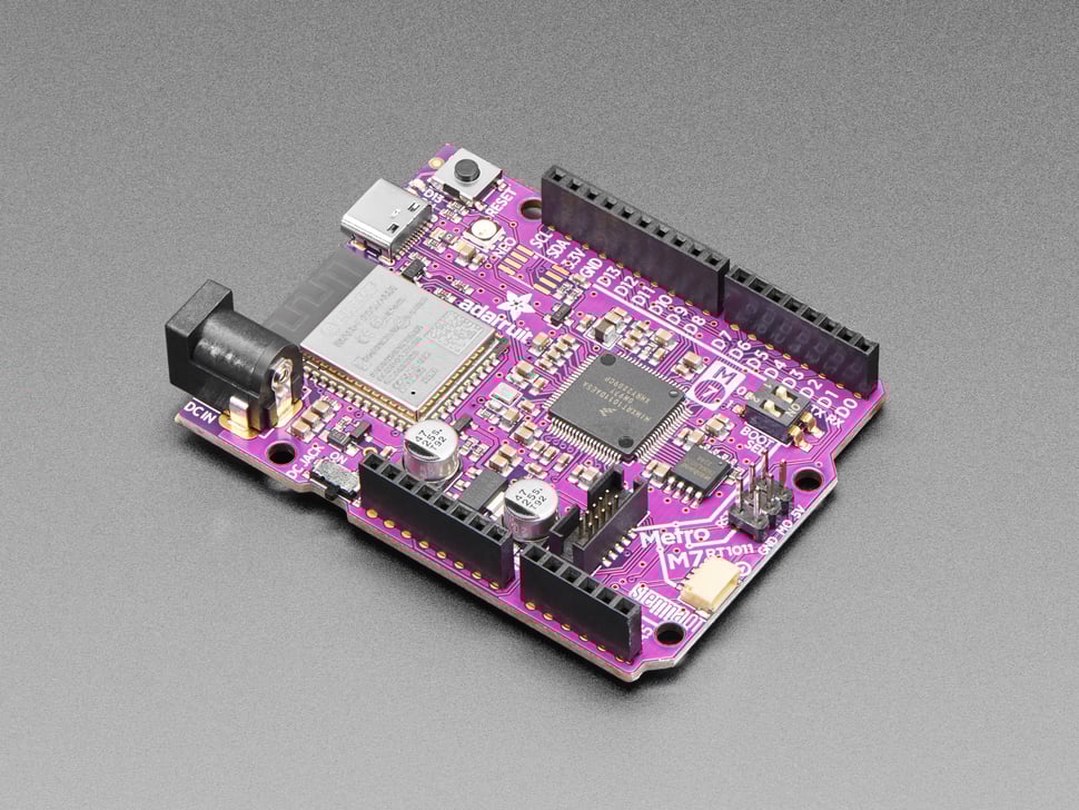
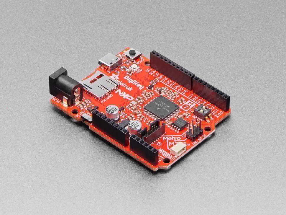
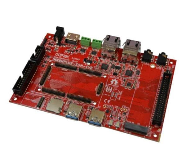
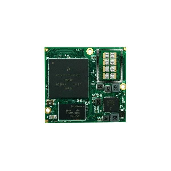
Our MCU will be i.MX RT1020 Cortex M7 from NXP (That will be my frist non arduino based project - fun).
Arduino interface
Development board (Revision A3) contains Arduino interface. We will have to use most of available connections.
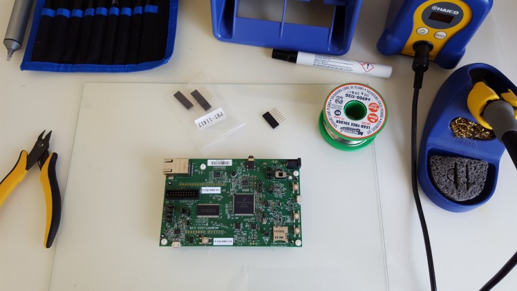
The dev board will not have the connectors assembled. You will have to solder them to the board. The GND pins (J20) will require more heat due to large ground plain ( It took me some time to understand why the soldinerg of those 2 pins have been so difficult :) )
The correct pin layout can be found in MCUXpresso
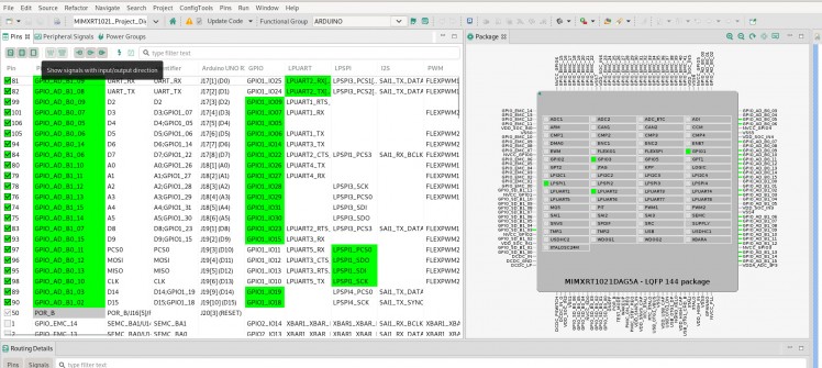
It is almost accurate except for pins D14 and D15.
If you check the schematics you will notice that D14 and D15 are assigned to different pads on GPIO3 instead of GPIO1 (as all the others) -[That misconfiguration has been detected during distance sensors test. I have used D14 as a trigger for the sensor - Test8 - distance sensors - few hours in debugging mode due to "AD" instead of "SD" :( ]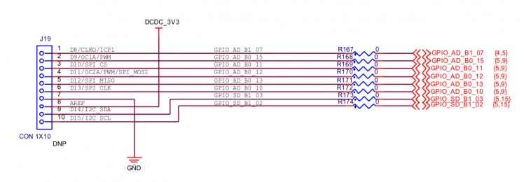
To make it more fun pin D5 and D6 are used by OpenSDA Interface. To use them as GPIO you have to remove jumpers from connectors J25 and J26 (it has changed on revision B of dev board) [It took me a long time to understand why D6 is set high regarding any configuration. The NXP support team has provided me with schematic for reve A3 - very useful forum]
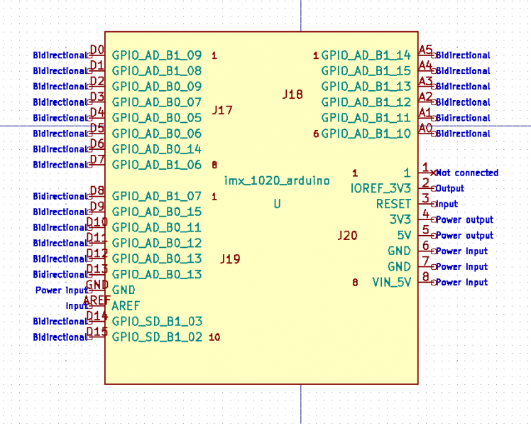
My KiCad symbol with pads and Arduino names
Coding
My We will have to create 2 different drivers:
- display -> drivers/amc/max7219
- distance sensor -> drivers/amc/hc_sr04
And one time util
- time calculation -> drivers/amc/time
Main behaviour (only MVP) is located at source
Display Driver
I have used a module with MAX7219 and 8-Digit, 8-Segment LED Display.
VCC ................................4V to 5V
DIN, CLK, LOAD, CS ..........-0.3V to 6V
We should be able to power it from 5V and use 3.3V logic to handle DIN, CLK, CS.
The frame is 16 bits long
1-7 Data
8-11 Address
12-15 Not used
You have to send 2 bytes: first with address and second with value. I would suggest to referring to the MAX7219 data sheet for further details.
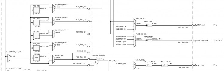
The SPI interface LP_SPI1 has to be configured to have max 10MHz on CLK
You will have to change the clocks diagram in MCUXpresso to use a 24Mhz clock with divider 4. It will provide you with 6Mhz clock on LP_SPI
After initialization you have to set number of bits to transfer to 16
- lpspi_master_config_t masterConfig;
- LPSPI_MasterGetDefaultConfig(&masterConfig);
- //MAX7219 requires 16 bit per frame
- masterConfig.bitsPerFrame = 16;
and send data in from of
- lpspi_transfer_t lpspiTransfer;
- uint8_t txData[20] = { 0 };
- lpspiTransfer.txData = txData;
- lpspiTransfer.rxData = NULL;
- lpspiTransfer.configFlags = kLPSPI_MasterPcs0 | kLPSPI_MasterByteSwap;
- lpspiTransfer.dataSize = 2; //we will send only 2 bytes
- txData[0] = 0x0a; //address - intensity
- txData[1] = 0x05; //value (~30% brightness)
- LPSPI_MasterTransferBlocking(LPSPI1, &lpspiTransfer);
The driver is able to send data but for some reason the initialization doesn't work as it should (extra debugging will be required)
Distance sensor
The distance ultrasonic distance sensor HC-SR04 allows you to measure distance in range of 2cm - 4m.
It is as well 5V device
VCC 5V
Trigger 5V (can be controlled by 3.3V gpio - TTL logic )
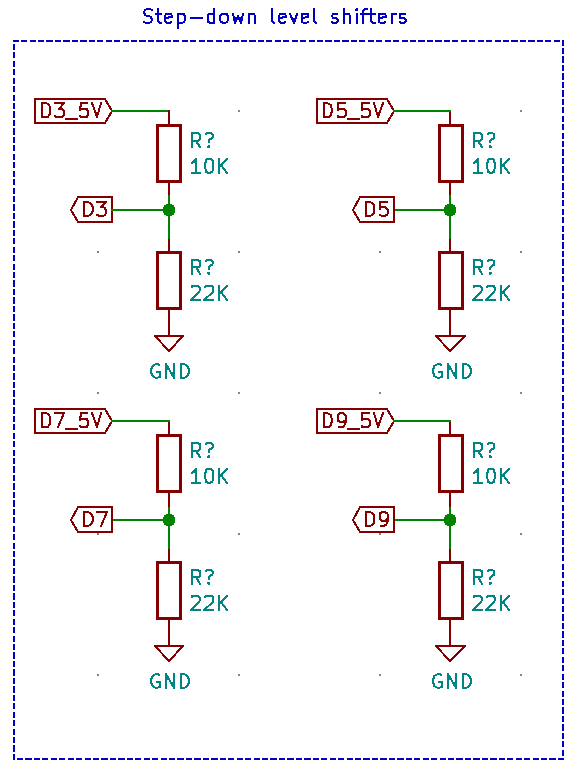
Echo 5v (can not be controlled by 3.3V - I know that from experience as I have destroyed pin D2 pad GPIO_AD_BO_09 - rest in peace :( ) - step down level shifter will be required
The HC-SR04 will send 8, 40khz pulses after the trigger pin is set to high for at least 10us.
If the pulse reflects back, it will set Echo pin to high for the duration between send and receive. If we know the speed of sound, we can calculate distance based on that duration
Main formula -> Echo high level time * 340M/S / 2
You can use simplified formula as well: EchoHigh_us/58 (I will allow you to do the math)
The driver will use interrupts on specific pin triggered by rising and falling edge as we have to measure the duration of that pulse.
- gpio_pin_config_t echoPinConfig = { kGPIO_DigitalInput, 0, kGPIO_IntRisingOrFallingEdge };
- GPIO_PinInit(GPIO1, echoPin, &echoPinConfig);
The interrupt handler will start and stop our timer
- void HC_SR04_IRQHandler(void) {
- if (wait) {
- if (rising) {
- TIME_StartMicroTimer();
- rising = false;
- } else {
- HC_SR04_timerDuration = TIME_StopMicroTimer();
- rising = true;
- wait = false;
- }
- }
- //reset all
- GPIO_PortClearInterruptFlags(GPIO1, 0xFFFFFFFF);
- SDK_ISR_EXIT_BARRIER;
- }
That leads us to our timer
Time
The time driver(util) will use one of the GPT (General Programmable Timer) [the rt1020 has 2 of those].
I would like to have a 1us counter handle by GPT interrupt. To do so we have to setup the clocks:

With GPT equal to 25Mhz we can expect 25 events pre microseconds.
Now we have to configure the timer
- gpt_config_t gptConfig;
- GPT_GetDefaultConfig(&gptConfig);
- GPT_Init(GPT1, &gptConfig);
- GPT_SetOutputCompareValue(GPT1, kGPT_OutputCompare_Channel1, 24);
The most important part is to correctly set up compare value. In that case with default config and compare value set to 24 we will have an interrupt every 1us (I have assumed that it should be 25 but it is not ? - check with scope). The accurate measurements are required for distance calculation.
Our interrupt handler have 2 functionality:
- delay (countdown tick_counter)
- time measurements in us (TimeDuration struct)
- void TIME_TickHandler(void) {
- /* Clear interrupt flag.*/
- GPT_ClearStatusFlags(GPT1, kGPT_OutputCompare1Flag);
- if (tick_counter != 0U) {
- tick_counter--;
- }
- if (timerEnabled) {
- timerDuration.microseconds++;
- if (timerDuration.microseconds == MICROSECONDS_PER_HOUR) {
- timerDuration.hours++;
- timerDuration.microseconds == 0;
- }
- }
- /* Add for ARM errata 838869, affects Cortex-M4, Cortex-M4F, Cortex-M7, Cortex-M7F Store immediate overlapping
- exception return operation might vector to incorrect interrupt */
- #if defined __CORTEX_M && (__CORTEX_M == 4U || __CORTEX_M == 7U)
- __DSB();
- #endif
- }
Box Assemble
Process took longer than expected. Manually building boxes was very labour intensive :). Next time: 3d printing
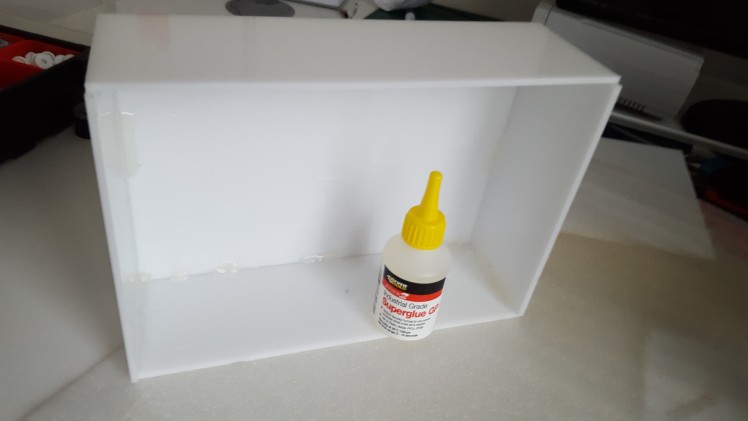
The main box has 4 elements all cut out from one large 3mm white gloss acrylic.
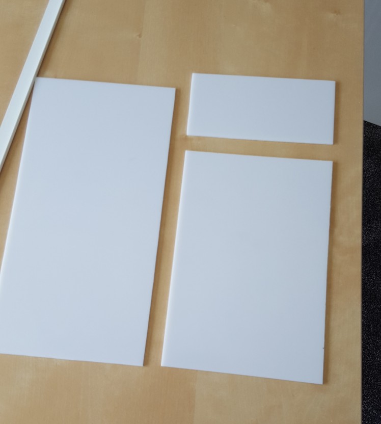
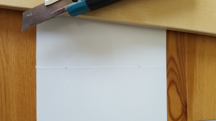
The process of cutting acrylic is very simple:
- measure required size
- using a scoring knife, cut a narrow groove
- bend one side of the sheet
Next part is to glue them together. I have used hot glue to keep everything in one place
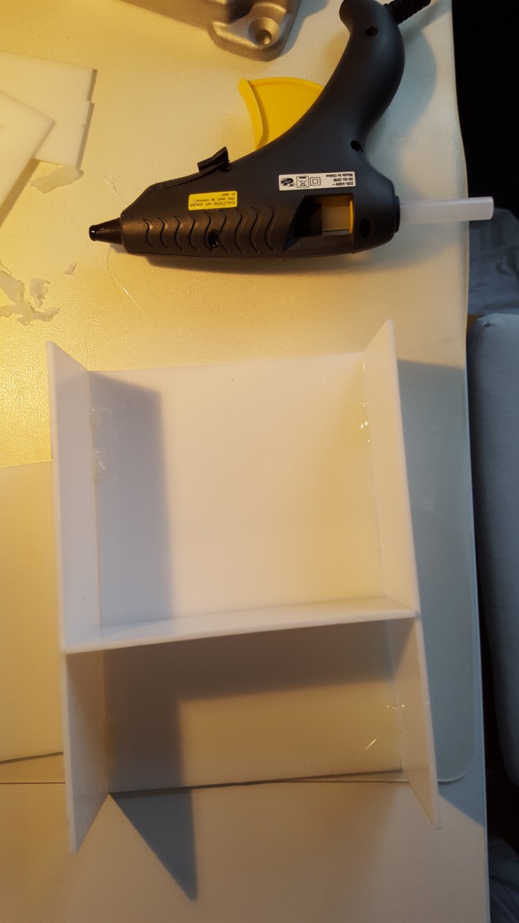
and super glue to improve the strength of the bond.
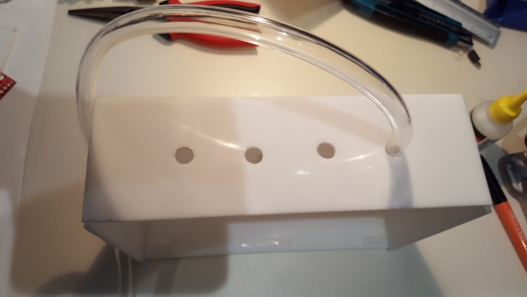
Next step is to cut 4 holes of 10mm diameter

11mm Clear Flexible PVC Tubing will fit perfectly
Lid
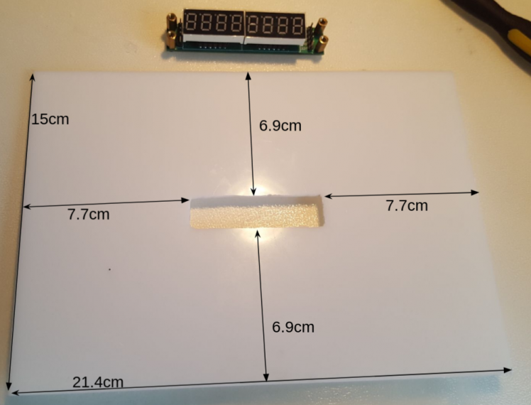
Now it is time to create 4 enclosures for our distance sensors. I will use a similar technique with 1mm acrylic

We will have to drill few holes to keep the top lid connected
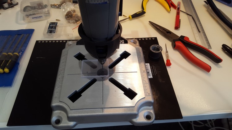
using 2 brass Spacer
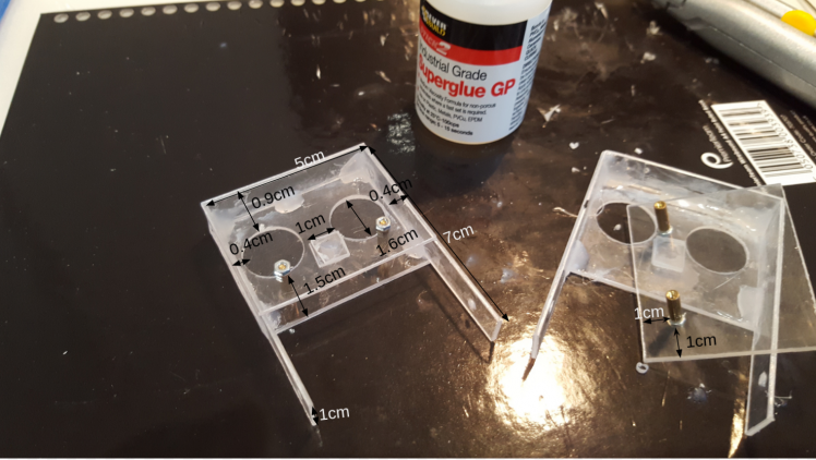
finally all what's left is to paint: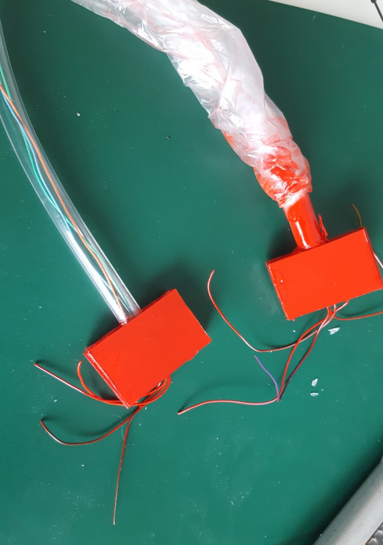
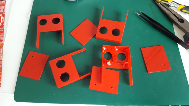
final assembly
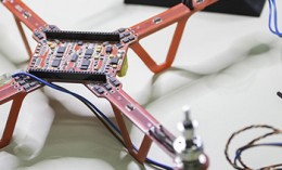
Electronics
To connect all the components with rt1020 dev board I have created a prototype shield using an Arduino compatible breakout board pcb (I don't have sufficient time to manufacture a custom pcb). The soldering took around 6 hours.
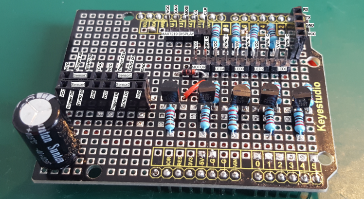
In that design we have to include
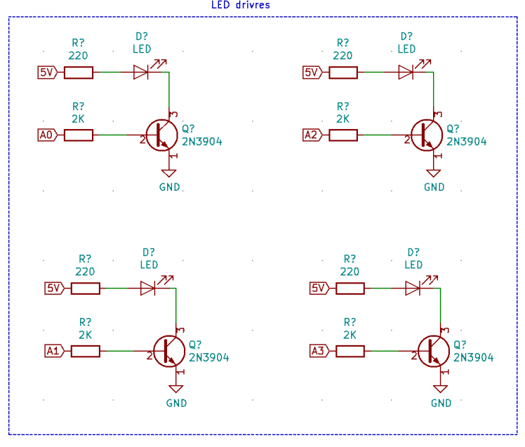
4 drivers for our leds
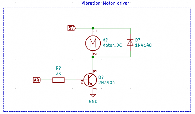
1 motor driver
4 step down level shifters
Note: large Capacitor is connected between GND and VCC to stabilize voltage.
For schematics please refer to github repo with KiCad project
Shield tests
All the components have been connected in steps to prevent any issues (fortunatlelly the board has been floweless :) )
Test 1 - System test without shield
Test 2 - Power with shield
Test 3 - Led test
The failure was due to pin misconfiguration inside the code
Test 4 - Motor
Similar issue to leds - misconfiguration in code
Test 5 - Display
Test 6 - Distance sensors
The failur is due to pin D14 and invalid values inside MCUXpress (GPIO1 instead of GPIO3)
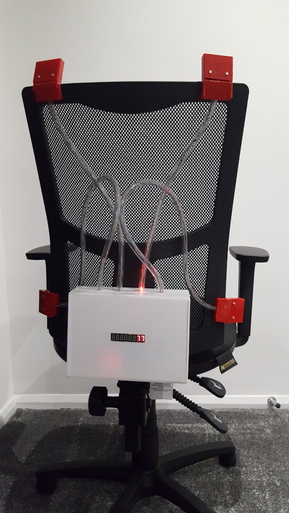
final result
What next
3 weeks jurney has come to an end. It has been very intresting challange. I have learn a lot and now it is time to move to some other projects :).
For the future improvments:
- Furhter calibrations are required. The current control is very simplistic.
- Power consumption has to be improved
- Display drivre requirs furhter debugging to fix initalization
- It would be interesting to use RTOS instead of all that blocking
- The android app to read the data from the unit should be developed
Schematics, diagrams and documents
Code
Credits
Related products


Leave your feedback...