
Dht11 Temperature And Humidity Plot And Visual Instruments

Made by Ron / Home Automation / Sensors / Weather
About the project
Multichannel data: Monitor, plot and show in visual instruments on your Desktop - Temperature and Humidity from DHT11 - quick and easy!
Project info
Difficulty: Easy
Estimated time: 1 hour
License: GNU General Public License, version 3 or later (GPL3+)
Items used in this project

Software apps and online services
Story
DTH11/DTH21/DTH22 and AM2301 are very popular combined Temperature and Humidity Arduino sensors.
I already made one tutorial on how to use them and send text information for the Temperature and Humidity over Serial Port.
In this tutorial I will show you how you can use Packet communication and display the data in visual Thermometer and Gauge in Visuino.
Step 1: Components
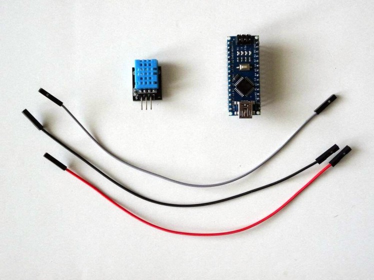
- One Arduino compatible board (I use Arduino Nano, because I have one, but any other will be just fine)
- One DHT11 Sensor module I got from this cheap 37 sensors set
- 3 Female-Female jumper wires
1 / 5 • Picture 1

Picture 1

Picture 2

Picture 3

Picture 4

Picture 5
- Connect Ground (Black wire), Power (Red wire), and Data (Gray wire) to the DHT11 Module (Picture 1 shows 2 different types of DHT11 sensor modules. As you can see the pins may differ, so connect carefully!)
- Connect the other end of the Ground wire (Black wire) to Ground pin of the Arduino board (Picture 2)
- Connect the other end of the Power wire (Red wire) to the 5V power pin of the Arduino board (Picture 2)
- Connect the other end of the Data wire (Gray wire) to Digital pin 2 of the Arduino board (Picture 3, and 4)
- Picture 5 shows where are the Ground, 5V Power, and Digital 2 pins of the Arduino Nano
1 / 2 • Picture 1

Picture 1

Picture 2
To start programming the Arduino, you will need to have the Arduino IDE installed from here: http://www.arduino.cc/ .
Please be aware that there are some critical bugs in Arduino IDE 1.6.6.
Make sure that you install 1.6.7 or higher, otherwise this Tutorial will not work!
The Visuino: https://www.visuino.com also needs to be installed.
- Click on the "Tools" button on the Arduino component (Picture 1) in Visuino
- When the dialog appears, select Arduino Nano as shown in Picture 2
1 / 2 • Picture 1

Picture 1

Picture 2
- Type "dht" in the Filter box of the Component Toolbox then select the "Humidity and Thermometer DHT11/21/22/AM2301" component (Picture 1), and drop it in the design area
- Connect the "Sensor" pin of the HumidityThermometer1 component to the "Digital" input pin of the Digital[ 2 ] channel of the Arduino component (Picture 2)
1 / 4 • Picture 1

Picture 1

Picture 2

Picture 3

Picture 4
- Type "pac" in the Filter box of the Component Toolbox then select the "Packet" component (Picture 1), and drop it in the design area
- Click on the "Tools" button of the Packet1 component(Picture 2)
- In the Elements editor, double click 2 times on the Binary Analog Element to add 2 of them (Picture 3, and 4)
1 / 3 • Picture 1

Picture 1

Picture 2

Picture 3
- Select the first element in the Elements editor(Picture 1)
- In the Object Inspector set the value of the Name property to "Temperature" (Picture 1)
- In the Object Inspector, for the Instrumentation property, click on the "Down Arrow" and select the "Thermometer" from the list(Picture 2)
- In the Object Inspector expand the "Instrument" property, then the "Scale" sub property (Picture 3)
- Set the "Auto" sub property to False to disable the automatic scaling (Picture 3)
- Set the "Min" sub property to the minimal temperature that we will display as example -20 (Picture 3)
- Set the "Max" sub property to the maximal temperature that we will display as example 100 (Picture 3)
1 / 2 • Picture 1

Picture 1

Picture 2
- Select the second element in the Elements editor (Picture 1)
- In the Object Inspector set the value of the Name property to "Temperature" (Picture 1)
- In the Object Inspector expand the "Instrument" property, then the "Scale" sub property (Picture 2)
- Set the "Auto" sub property to False to disable the automatic scaling (Picture 2)
- Set the "Max" sub property to 100 (Picture 2)
1 / 2 • Picture 1

Picture 1

Picture 2
To make sure that Visuino will find the starting point of the packet, we need to have a unique header. The Packet component uses special algorithm to ensure that the header marker does not appear in the data.
- Select the Packet1 component (Picture 1)
- In the Object Inspector expand the HeadMarker property (Picture 1)
- In the Object Inspector click on the "..." button (Picture 1)
- In the Bytes editor type some numbers, as example 55 55
- Click on the OK button to confirm and close the editor
1 / 3 • Picture 1

Picture 1

Picture 2

Picture 3
- Connect the "Out" output pin of the Packet1 component to the "In" input pin of the "Serial[ 0 ]" channel of the "Arduino"component(Picture 1)
- Connect the "Temperature" output pin of the HumidityThermometer1 component to the "In" pin of the Elements.Temperature element of the Packet1 component (Picture 2)
- Connect the "Humidity" output pin of the HumidityThermometer1 component to the "In" pin of the Elements.Humidity element of the Packet1 component (Picture 3)
1 / 2 • Picture 1

Picture 1

Picture 2
- In Visuino, Press F9 or click on the button shown on Picture 1 to generate the Arduino code, and open the Arduino IDE
- In the Arduino IDE, click on the Upload button, to compile and upload the code (Picture 2)
1 / 6 • Picture 1

Picture 1

Picture 2

Picture 3

Picture 4

Picture 5

Picture 6
- In Visuino select the ComPort, and then click on the "Format:" drop down box, and select Packet1 (Picture 1)
- Click on the "Connect" button (Picture 2)
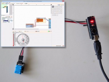
- If you select the "Instruments" tab, you will see the Thermometer and the Gauge showing the Temperature and Humidity (Picture 3)
- If you select the "Scope" tab, you will see the the Scope plotting the Temperature and Humidity over time (Picture 4)
You can see the connected and running Humidity and Temperature sensor on Picture 5.
Congratulations! You have created a Temperature and Humidity measuring project in Arduino, with Visual Instrumentation.
On Picture 6 you can see the complete Visuino diagram.
Also attached is the Visuino project, that I created for this Tutorial. You can download and open it in Visuino: https://www.visuino.com
Credits
Related products


Leave your feedback...