
Dht11 Temperature And Humidity I2c 2 X 16 Lcd Display

Made by Ron / Displays / Home Automation / Sensors / Weather
About the project
Display THD11 measured Temperature and Humidity on I2C LCD Display - quick and easy!
Project info
Difficulty: Easy
Estimated time: 1 hour
License: GNU General Public License, version 3 or later (GPL3+)
Items used in this project
Hardware components

Software apps and online services
Story
I already made two Tutorials on how to use DTH11/DTH21/DTH22 and AM2301 Temperature and Humidity sensors with Arduino, and you can find them here and here . I also made Tutorial on how to use I2C LCD Character Display, and one on how to use a directly connected LCD Character Display .
Here I will show you how you can use I2C LCD Character Display to display Temperature and Humidity measured by DHT11 sensor. The same steps can be followed to implement the project with directly connected LCD display.
In the previous Tutorials, we just sent some text to be directly displayed in the LCD Display in the order the characters arrived. Visuino allows the information to also be displayed in predefined fields at specific positions. In addition, Visuino allows visually to create and use custom characters in the display. In this Tutorial, we will use all of these features to make a cool Temperature and Humidity LCD display.
Step 1: Components
1 / 2 • Picture 1

Picture 1

Picture 2
- One Arduino compatible board (I use Arduino Nano, because I have one, but any other will be just fine)
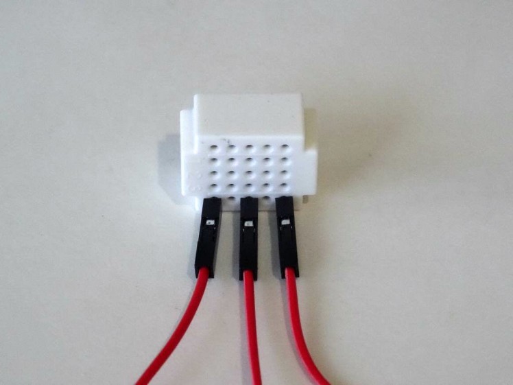
- One DHT11 Sensor module I got from this cheap 37 sensors set
- One I2C 16x2 LCD Display (Back side of the LCD with the I2C adapter showed on Picture 2)
- One small Breadboard (Any breadboard can be used, or any other way to connect 3 wires together)
- 3 Female-Male jumper wires
- 5 Female-Female jumper wires
1 / 3 • Picture 1

Picture 1

Picture 2

Picture 3
- Connect Ground (Black wire), Power (Red wire), SDA (Green wire), and SCL (Yellow wire) to the LCD Module (Picture 1)
- Connect the other end of the SDA wire ire (Black wire) to Ground pin of the Arduino board (Picture 2)
- Connect the other end of the SDA wire(Green wire) to SDA/Analog pin 4 of the Arduino Nano board (Picture 2)
- Connect the other end of the SCL wire (Yellow wire) to SCL/Analog pin 5 of the Arduino Nano board (Picture 2)
- Connect another Female-Male Power wire (Red wire) to the 5V Power pin of the Arduino board (Picture 2), and leave the Male end unconnected
- Picture 3 shows where are the Ground, 5V Power, SDA/Analog pin 4, and SCL/Analog pin 5 pins of the Arduino Nano
1 / 4 • Picture 1

Picture 1

Picture 2

Picture 3

Picture 4
- Connect Female-MalePower (Red wire), connect Female-Female Ground (Black wire), and Data (Gray wire) to the DHT11 Module (Picture 1 shows 2 different types of DHT11 sensor modules. As you can see the pins may differ, so connect carefully!)
- Connect the other end of the Ground wire (Black wire) to Ground pin of the Arduino board (Picture 2 and 3)
- Connect the other end of the Data wire (Gray wire) to Digital pin 2 of the Arduino board (Picture 2, and 3)
- Picture 4 shows in Red where are the Ground, and Digital 2 pins of the Arduino Nano (In Blue are shown the connections made in the previous step)
Connect the Male ends of the 3 Power wires (Red wires) - from the Display, the DHT11 Module, and the Arduino together as example with the help of a Breadboard (Picture 1) - In my case I used a small Breadboard.
Step 5: Start Visuino, and select the Arduino Board type
1 / 2 • Picture 1

Picture 1

Picture 2
To start programming the Arduino, you will need to have the Arduino IDE installed from here: http://www.arduino.cc/ .
Please be aware that there are some critical bugs in Arduino IDE 1.6.6.
Make sure that you install 1.6.7 or higher, otherwise this Tutorial will not work!
The Visuino: https://www.visuino.com also needs to be installed.
- Start Visuino as shown in the first picture
- Click on the "Tools" button on the Arduino component (Picture 1) in Visuino
- When the dialog appears, select Arduino Nano as shown in Picture 2
1 / 3 • Picture 1

Picture 1

Picture 2

Picture 3
- Type "lcd" in the Filter box of the Component Toolbox then select the "Liquid Crystal Display (LCD) - I2C" component (Picture 1), and drop it in the design area
- Click on the "Tools" button (Picture 2) to open the Elements editor (Picture 3)
1 / 4 • Picture 1

Picture 1

Picture 2

Picture 3

Picture 4
We will add a Text field with the description of the value, and Analog field to display the value for the Temperature and Humidity values.
First we will add Description and value fields for the Temperature:
- Add Text field for the Temperature description text by double clicking on the "Text Field" in the right window of the "Elements" editor (Picture 1)
- In the Object Inspector set the "InitialValue" property of the element to "Temp:" (Picture 1) - This will specify the text to be displayed
- In the Object Inspector set the "Width" property of the element to 10 (Picture 1) - This will specify that the text field will be no bigger than 10 characters
- Add Analog field for the Temperature value double clicking on the "Analog Field" in the right window of the "Elements" editor (Picture 2)
- In the Object Inspector set the "Column" property of the element to 10 (Picture 2) - This will specify the starting column of the field
- In the Object Inspector set the "Precision" property of the element to 1 (Picture 2) - This will specify the number of digits after the decimal point
- In the Object Inspector set the "Width" property of the element to 4 (Picture 2) - This will specify that the field will be no bigger than 4 characters
Next we will repeat the same steps for the Humidity:
- Add Text field for the Humidity description text by double clicking on the "Text Field" in the right window of the "Elements" editor (Picture 3)
- In the Object Inspector set the "InitialValue" property of the element to "Humidity:" (Picture 3)
- In the Object Inspector set the "Row" property of the element to 1 (Picture 3) - This will specify that the field will be shown in the second row of the Display
- In the Object Inspector set the "Width" property of the element to 10 (Picture 3)
- Add Analog field for the Humidity value by double clicking on the "Analog Field" in the right window of the "Elements" editor (Picture 4)
- In the Object Inspector set the "Column" property of the element to 10 (Picture 4)
- In the Object Inspector set the "Precision" property of the element to 1 (Picture 4)
- In the Object Inspector set the "Row" property of the element to 1 (Picture 4)
- In the Object Inspector set the "Width" property of the element to 4 (Picture 4)
1 / 3 • Picture 1

Picture 1

Picture 2

Picture 3
The LCD display does not have Degree symbol, so we will define our own. For this, first we will define a symbol, and then display it.
- Add field to define a custom character by double clicking on the "Define Custom Character" in the right window of the "Elements" editor (Picture 1)
- In the Object Inspector, select the "Pattern" property, and click on the "..." button next its value (Picture 1)
- In the Pixel Editor, draw the shape of the Degree symbol as shown in Picture 2. You can use the mouse or the arrows to move around, and the "Spacebar" key to set or clear a pixel
- Close the dialog by clicking on the "OK" button (Picture 2)
- Add a field do display the custom character at specific location by double clicking on the "Custom Character Field" in the right window of the "Elements" editor (Picture 3)
- In the Object Inspector set the "Column" property of the element to 15 (Picture 3)
1 / 2 • Picture 1

Picture 1

Picture 2
- Add Text field for the % text by double clicking on the "Text Field" in the right window of the "Elements" editor (Picture 1)
- In the Object Inspector set the "InitialValue" property of the element to "%" (Picture 1)
- In the Object Inspector set the "Column" property of the element to 15 (Picture 1)
- In the Object Inspector set the "Row" property of the element to 1 (Picture 1)
- Connect the "Out" pin of the LCD component to the to the "In" pin of the I2C channel of the Arduino component (Picture 2)
1 / 4 • Picture 1

Picture 1

Picture 2

Picture 3

Picture 4
- Type "dht" in the Filter box of the Component Toolbox then select the "Humidity and Thermometer DHT11/21/22/AM2301" component (Picture 1), and drop it in the design area
- Connect the "Temperature" output pin of the HumidityThermometer1 component to the "In" pin of the Elements.AnalogField1 element of the LiquidCrystalDisplay1 component (Picture 2)
- Connect the "Humidity" output pin of the HumidityThermometer1 component to the "In" pin of the Elements.AnalogField2 element of the LiquidCrystalDisplay1 component (Picture 3)
- Connect the "Sensor" pin of the HumidityThermometer1 component to the "Digital" input pin of the "Digital[ 2 ]" channel of the Arduino component (Picture 4)
1 / 2 • Picture 1

Picture 1

Picture 2
We can use the project as it is, however it will refresh the LCD very fast all the time. It is better if the LCD is updated as example once a second. For this we will add a clock component to clock the reading from the sensor and the updating of the LCD.
- Type "clock" in the Filter box of the Component Toolbox then select the "Clock Generator" component (Picture 1), and drop it in the design area
- Connect the "Out" pin of the ClockGenerator1 component to the "Clock" input pin of the HumidityThermometer1 component (Picture 2)
1 / 2 • Picture 1

Picture 1

Picture 2
- In Visuino, Press F9 or click on the button shown on Picture 1 to generate the Arduino code, and open the Arduino IDE
- In the Arduino IDE, click on the Upload button, to compile and upload the code (Picture 2)
1 / 2 • Picture 1

Picture 1

Picture 2
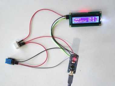
Congratulations! You have completed the project.
Picture 1 shows the connected and powered up project. As you can see on the picture the Display will show the temperature and the Humidity.
On Picture 2 you can see the complete Visuino diagram.Also attached is the Visuino project, that I created for this Tutorial. You can download and open it in Visuino: https://www.visuino.com
Credits
Related products


Leave your feedback...