
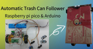
Create An Automated Trash Can With Raspberry Pi Pico
Made by Elecrow / Artificial intelligence / Environmental Sensing / Home Automation / IoT
About the project
This project is a trash can designed to accompany you wherever you go. It harnesses the power of two key components: the Raspberry Pi Pico and Arduino. If you're seeking a solution to streamline your waste management process, I'm confident you'll find this project quite appealing.
Project info
Difficulty: Moderate
Platforms: Elecrow
Estimated time: 3 hours
License: GNU General Public License, version 3 or later (GPL3+)
Items used in this project
Hardware components


View all
Story
Have you ever had to go out of your way to find a trash can when you needed to dispose of something? It's really inconvenient to carry your trash around with you until you find a bin! So, I thought, what if I could make a trash can that followed me around instead? That way, I'd never have to worry about finding a bin again!
I turned this idea into reality with my "Automated Following Trash Can" project. Now, wherever I go, my trusty trash can is right beside me, making disposal a breeze. Plus, I whipped up this project in just half a day using Raspberry Pi Pico and Arduino. Curious? Read on!
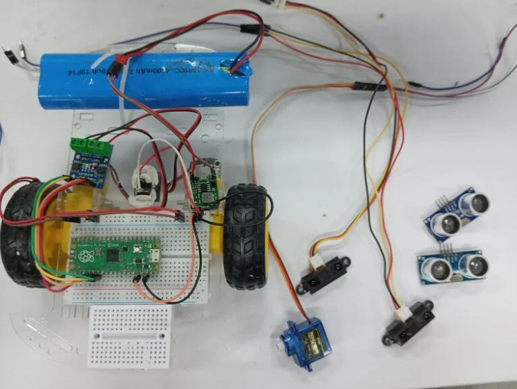
Raspberry Pi Pico x1 --->I use it as the main controller
Buck Converter Module x1 --->Since the maximum voltage that all the hardware I'm using can withstand is 5V, and the battery I currently have is 7.4V, I have decided to use a voltage regulator module to help me provide a stable 5V power supply.
L9110 Motor Driver Module x1 --->This is a very useful module that helps me to drive the wheels.
Infrared Proximity Sensor-GP2Y0A21YK0F x2 --->I need to use two of these modules because I need to use them to detect if the person it's following is making a left or right turn. When a left turn occurs, the infrared module fixed on the left side will detect an object, while the one on the right will not. At this point, the main control chip will control the trash can to turn left.
HC-SR04 Ultrasonic Sensor Module x2 --->I use it to detect the distance between the trash can and the person it's following. When the distance exceeds 20cm, the wheels of the trash can start moving, trying to maintain a distance of 15-20cm from the person it's following.
Robot Car Chassis x1 --->If you want to make the trash can move, the easiest way is to give it a small car chassis!
Useless Box x1 --->This is just a random cardboard box I found, but you can use any small box of your choice. Any shape will do.
Battery x1 --->Since I only have a 7.4V battery, I have to use it as the power source for my entire project.
SG90 Servo Motor x1 --->This servo module helps me to open the lid of the trash can. It's very useful!
Switch Button x1 --->This switch is what I use to control the power on and off.
Breadboard x1 --->I also included a breadboard in my setup. While some may prefer to skip it for a messier setup, I find it very useful for wiring and organization. That's why I decided to use it.
Dupont Wires xN --->This is something we use very frequently, so please prepare more of them if possible.
Step 1: Make a Cardboard Box for Our Car
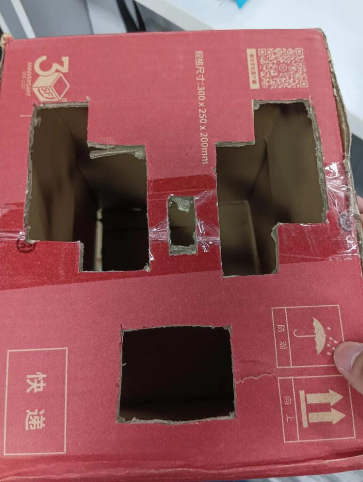
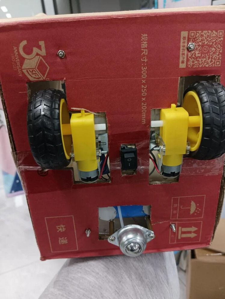
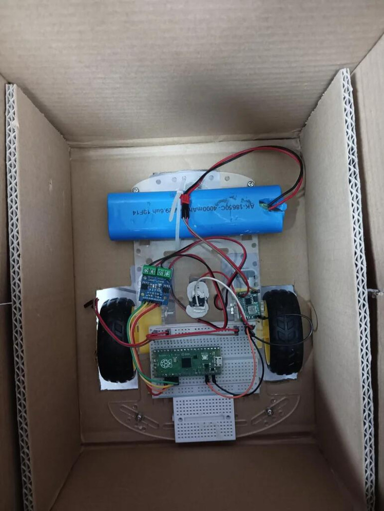
First, find a cardboard box that is roughly the same size as the robot car chassis. Then, use scissors to cut holes in the bottom of the cardboard box for the three wheels and motors of the car. This process requires extreme caution and attention to safety. It's best to measure and cut slowly, so as not to cut too much or accidentally damage the box. After making the box, we can place the robot car chassis inside it and use screws and nuts to secure the chassis to the cardboard box.
Step 2: Connect the Circuit According to the Circuit Diagram
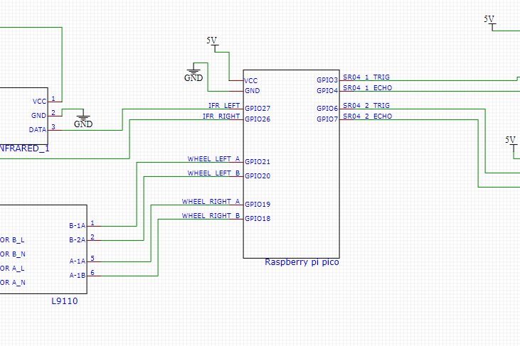
If you take a look at the circuit diagram for this project, you'll see that it's actually pretty simple. You only need 5 modules, and there are only 14 wires to connect (not counting the power and ground connections). Once you've connected the wires, you just need to fix the modules in place.
I attached two infrared proximity sensor modules to the left and right sides of the cardboard box to detect if the object being followed is turning left or right. Then, I fixed the ultrasonic sensor module in the middle of the front of the cardboard box to detect the distance between the car and the object in front of it. I even made two holes in the box to make it look like a cute pig's nose!
I also placed an ultrasonic sensor module on the edge of the box lid to detect if the lid is open. This placement allows for more accurate detection.
As for the servo motor, I fixed it inside the box and attached it to a disposable chopstick with hot melt glue to make it long enough to open the lid.
Step 3: Arduino Programming
This project may appear complex at first glance, but in reality, the code is quite simple. It involves collecting data from the sensor modules, processing it, and then controlling the movement of the car's wheels based on that data. The source code for the entire project will be provided at the end of the article. In the following sections, I will explain the code line by line, so that you can quickly understand and create your own automatic follow-me trash can.
#include "Ultrasonic.h"
#include "wheel.h"
#include "RPi_Pico_TimerInterrupt.h"
#include <Servo.h>
The above code is the header file section of the Arduino code for the project. It includes the necessary libraries for the project, such as "Ultrasonic.h", which provides functions for using the ultrasonic sensor module, "wheel.h", which provides functions for controlling the movement of the car's wheels, "RPi_Pico_TimerInterrupt.h", which provides functions for interrupt handling using timers, and <Servo.h>, which provides functions for controlling the servo motor.
These libraries provide various functions and methods that will be used in the main code to control the car's movement and detect obstacles.
#define Left_eye 27
#define Right_eye 26
#define TIMER0_INTERVAL_MS    100
#define TIMER1_INTERVAL_MS    33
The above code defines some constants that will be used in the main code.
"Left_eye" and "Right_eye" are constants that hold the GPIO pin numbers for the left and right infrared proximity sensor modules.
"TIMER0_INTERVAL_MS" and "TIMER1_INTERVAL_MS" are constants that hold the interval time (in milliseconds) for two different timers that will be used in the code.
These constants make the code more readable and easier to modify, as their values can be changed in one place and their effects will be reflected throughout the code.
int cover_stat = 0;
int SR_Distance = 0;
int Cover_Distance = 0;
uint16_t value1 = 0;
uint16_t range1 = 0;
uint16_t value2 = 0;
uint16_t range2 = 0;
The above code declares several variables that will be used in the main code.
"cover_stat" is a variable used to store the status of the trash can cover. It is initialized to 0, which represents a closed cover.
"SR_Distance" and "Cover_Distance" are variables used to store the distances measured by the ultrasonic sensor modules.
"value1", "range1", "value2", and "range2" are variables used to store the values and ranges measured by the infrared proximity sensor modules.
These variables will be updated throughout the code as the sensors detect changes in the environment.
RPI_PICO_Timer ITimer0(0);
RPI_PICO_Timer ITimer1(1);
Servo myservo;
The above code creates two timer objects, "ITimer0" and "ITimer1", using the "RPI_PICO_Timer" library. These timers will be used to trigger functions at regular intervals specified by the constants defined earlier.
The code also creates a "Servo" object named "myservo", which will be used to control the servo motor that opens and closes the trash can lid.
Ultrasonic ultrasonic(3,4);
Ultrasonic Cover_ultrasonic(6,7);
The above code creates two "Ultrasonic" objects using the "Ultrasonic" library. The first object is named "ultrasonic" and is connected to the HC-SR04 ultrasonic sensor module using GPIO pin 3 for trigger and pin 4 for echo.
The second object is named "Cover_ultrasonic" and is connected to another HC-SR04 ultrasonic sensor module using GPIO pin 6 for trigger and pin 7 for echo.
These objects will be used to measure the distances between the car and objects in front of it and also to detect if the trash can lid is open or closed.
bool TimerHandler0(struct repeating_timer *t)
{
 Cover_Distance = Cover_ultrasonic.Ranging(CM);
 cover_stat++;
 if((Cover_Distance<=20) && (Cover_Distance>1))
 {
  myservo.write(130);
  cover_stat = 0 ;
 }
 if(cover_stat>(3*1000/TIMER0_INTERVAL_MS))
 {
  myservo.write(10);
 }
 ITimer0.restartTimer();
 return true;
}
The above code defines a function named "TimerHandler0", which will be called by the first timer object, "ITimer0", at the interval specified by "TIMER0_INTERVAL_MS". This function is used to control the servo motor that opens and closes the trash can lid.
First, the function uses the "Cover_ultrasonic" object to measure the distance between the car and the trash can lid, and stores the result in the "Cover_Distance" variable. Then, the "cover_stat" variable is incremented, which is used to keep track of how long the lid has been open. If the "Cover_Distance" is less than or equal to 20 (indicating someone wants to dispose of trash and has their hand reaching towards the trash can with a distance less than 20cm), the "myservo" object is used to move the servo motor to an angle of 130 degrees (opening the lid). When the lid is opened, the "cover_stat" variable is incremented, and if it reaches the set time (3 seconds in your code), the servo motor is used to move the lid to an angle of 10 degrees (closing the lid).
Just a heads up, the angle needed to open the trash can lid may vary depending on the type of servo motor you're using. So, it's a good idea to test the angle required to open the lid with your particular servo motor before permanently fixing it in place. This will save you from any headaches later on!
If the "cover_stat" variable exceeds a certain threshold (calculated based on the timer interval), the "myservo" object is used to move the servo motor to an angle of 10 (which opens the lid).
Finally, the "ITimer0.restartTimer()" function is called to restart the timer, and the function returns "true".
bool TimerHandler1(struct repeating_timer *t)
{
 SR_Distance = ultrasonic.Ranging(CM);
 value1 = analogRead (Right_eye);
 range1 = get_gp2d12 (value1);
 value2 = analogRead (Left_eye);
 range2 = get_gp2d12 (value2);
 ITimer1.restartTimer();
 return true;
}
The above code defines another function named "TimerHandler1", which will be called by the second timer object, "ITimer1", at the interval specified by "TIMER1_INTERVAL_MS". This function is used to update the values of several variables based on the data collected by the sensor modules.
First, the "ultrasonic" object is used to measure the distance between the car and the object in front of it, and the result is stored in the "SR_Distance" variable.
Then, two infrared proximity sensor modules are used to measure the distances between the car and objects on the left and right sides of it. The analog readings from these sensors are stored in the "value1" and "value2" variables, respectively. The "get_gp2d12" function is then called to convert these readings to distances in centimeters, which are stored in the "range1" and "range2" variables.
Finally, the "ITimer1.restartTimer()" function is called to restart the timer, and the function returns "true".
bool follow_me_trashbin()
{
 if((range1<=100) && (range2>100))
 {
  wheel_right();
  Serial.println("<");
 }
 else if((range2<=100) && (range1>100))
 {
  wheel_left();
  Serial.println(">");
 }
 else if((range1 < 100) && (range2 < 100) || (SR_Distance < 10))
 {
  wheel_stop();
 }
 else if((SR_Distance > 20))
 {
  wheel_forword();
 }
 else if((range1>100) && (range2>100) && (SR_Distance<15) && (SR_Distance>10))
 {
  wheel_forback();
 }
 else
 {
  wheel_stop();
 }
 return true;
}
The above code defines the main function of the project, "follow_me_trashbin". This function uses the values of the variables updated by the timer functions to control the movement of the car's wheels.
The function first checks if an object is detected on only the left or right side of the car, and turns the car in the appropriate direction using the "wheel_right" or "wheel_left" functions. The direction is also printed to the serial monitor using "Serial.println".
If objects are detected on both sides of the car or if the car is too close to an object (as determined by the "range1" and "range2" variables), the car is stopped using the "wheel_stop" function.
If the car is far enough away from objects (as determined by the "SR_Distance" variable), it moves forward using the "wheel_forword" function.
If the car is too close to an object in front of it but not too close to objects on the sides of it, it moves backward using the "wheel_forback" function.
If none of the above conditions are met, the car is stopped using the "wheel_stop" function.
Finally, the function returns "true".
void setup()
{
 myservo.attach(9);
 myservo.write(10);

 wheel_pins_init();

 pinMode (Left_eye, INPUT);
 pinMode (Right_eye, INPUT);

 ITimer0.attachInterruptInterval(TIMER0_INTERVAL_MS * 1000, TimerHandler0);
 ITimer0.restartTimer();

 ITimer1.attachInterruptInterval(TIMER1_INTERVAL_MS * 1000, TimerHandler1);
 ITimer1.restartTimer();
}
The above code is the setup function of the Arduino code for the project. It initializes the necessary components and sets up the timers to trigger the interrupt functions at regular intervals.
First, the "myservo" object is attached to GPIO pin 9, and the servo motor is set to its initial position (which opens the lid).
Next, the "wheel_pins_init" function is called to initialize the GPIO pins used to control the car's wheels.
Then, the GPIO pins for the infrared proximity sensor modules are set to input mode using the "pinMode" function.
Finally, the two timer objects are set up to trigger the interrupt functions at the specified intervals using the "attachInterruptInterval" function, and the timers are started using the "restartTimer" function.
uint16_t get_gp2d12 (uint16_t value) {
  if (value < 10) value = 10;
  return ((67870.0 / (value - 3.0)) - 40.0);
}
The above code defines a function named "get_gp2d12", which is used to convert the analog readings from the infrared proximity sensor modules to distances in centimeters.
The function takes in an unsigned 16-bit integer value as a parameter, which represents the analog reading from the sensor module.
If the value is less than 10, it is set to 10 to avoid division by zero errors.
The function then uses a formula to convert the analog reading to a distance in centimeters, which is returned as an unsigned 16-bit integer.
The formula used is based on the datasheet of the Sharp GP2D12 sensor module, which uses a linear regression equation to convert the analog voltage output to distance.
void loop()
{
 follow_me_trashbin();
}
The above code is the loop function of the Arduino code for the project. It simply calls the "follow_me_trashbin" function repeatedly to control the movement of the car based on the sensor data.
The "follow_me_trashbin" function will continuously update the movement of the car based on the sensor data, so the loop will continue to execute as long as the Arduino board is powered on.
Leave your feedback...