
Convert Acceleration To Angle From Mpu6050 I2c Sensor

About the project
Arduino Nano and Visuino: Convert Acceleration to Angle From Accelerometer and Gyroscope MPU6050 I2C Sensor - quick and easy.
Project info
Difficulty: Easy
Platforms: Arduino, SparkFun, Visuino
Estimated time: 1 hour
License: GNU General Public License, version 3 or later (GPL3+)
Items used in this project
Hardware components

Software apps and online services
Story
A while ago I posted a tutorial on how you can connect MPU9250 Accelerometer, Gyroscope and Compass Sensor to Arduino Nano and program it with Visuino to send packet data and display it on a Scope and Visual Instruments.
The Accelerometer sends X, Y, and Z acceleration forces. Often however we need to convert the forces into X, Y, Z 3D angle to determine the 3D Orientation of the sensor. Quite few people requested such tutorial, and finally I have found time to make it.
Some people also asked how you can connect and use MPU6050 Accelerometer and Gyroscope Sensor, so I decided to use this module for the tutorial instead of the more complex and expensive MPU9250.
In this Tutorial, I will show you how easy it is to connect MPU6050 Accelerometer and Gyroscope Sensor to Arduino Nano, and program it with Visuino to convert the Acceleration into a 3D X, Y, Z Angle.
Step 1: Components
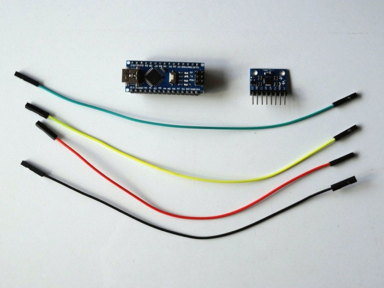
- One Arduino compatible board (I use Arduino Nano, because I have one, but any other will be just fine)
- One MPU6050 Acceleration Gyroscope Sensor Module
- 4 Female-Female jumper wires
1 / 4 • Picture 1

Picture 1

Picture 2

Picture 3

Picture 4
- Connect 5V VCC Power(Red wire), Ground(Black wire), SCL(Yellow wire), and SDA(Green wire) to the MPU6050 Module (Picture 1)
- Connect the other end of the Ground wire(Black wire) to a Ground pin of the Arduino Nano board (Picture 2)
- Connect the other end of the 5V VCC Power wire(Red wire) to the 5V power pin of the Arduino Nano board (Picture 2)
- Connect the other end of the SDA wire(Green wire) to SDA/Analog pin 4 of the Arduino Nano board (Picture 3)
- Connect the other end of the SCL wire(Yellow wire) to SCL/Analog pin 5 of the Arduino Nano board (Picture 3)
- Picture 4 shows where are the Ground, 5V Power, SDA/Analog pin 4, and SCL/Analog pin 5, pins of the Arduino Nano
1 / 2 • Picture 1

Picture 1

Picture 2
To start programming the Arduino, you will need to have the Arduino IDE installed from here: http://www.arduino.cc/.
Make sure that you install 1.6.7 or higher, otherwise this tutorial will not work!
The Visuino: https://www.visuino.com also needs to be installed.
- Start Visuino as shown in the first picture
- Click on the "Tools" button on the Arduino component (Picture 1) in Visuino
- When the dialog appears, select Arduino Nano as shown in Picture 2
1 / 4 • Picture 1

Picture 1

Picture 2

Picture 3

Picture 4
First we need to add components to control the MPU6050 Sensor, and to convert the X, Y, Z Acceleration into 3D X, Y, Z Angle:
- Type "6050" in the Filter box of the Component Toolbox then select the "Accelerometer Gyroscope MPU6000/MPU6050 I2C" component (Picture 1), and drop it in the design area (Picture 2)
- Type "angle" in the Filter box of the Component Toolbox then select the "Acceleration To Angle" component (Picture 2), and drop it in the design area (Picture 3)
- Click in the "Out" box of the "Accelerometer" box containing the X,Y, X Acceleration pins of the AccelerometerGyroscope1 component to start connecting all the Out pins at once (Picture 3)
- Move the mouse over the "X" input pin of the "In" box of the AccelerationToAngle1 component. The Visuino will automatically spread the wires so they will connect correctly to the rest of the pins (Picture 3)
- Connect the "Out" pin of the AccelerometerGyroscope1 component to the to the "In" pin of the I2C channel of the Arduino component (Picture 4)
1 / 3 • Picture 1

Picture 1

Picture 2

Picture 3
To send all the channels data over serial port from Arduino we can use the Packet component to packet the channels together, and display them in the Scope and Gauges in Visuino:
- Type "packet" in the Filter box of the Component Toolbox then select the "Sine Analog Generator" component (Picture 1), and drop it in the design area
- In the Object Inspector expand the "Head Marker"property (Picture 2)
- In the Object Inspector click on the "..." button (Picture 2)
- In the Bytes editor type some numbers, as example 55 55 (Picture 3)
- Click on the OK button to confirm and close the editor
1 / 5 • Picture 1

Picture 1

Picture 2

Picture 3

Picture 4

Picture 5
To send all the channels data over serial port from Arduino we can use the Packet component to packet the channels together, and display them in the Scope and Gauges in Visuino:
- Click on the "Tools" button of the Packet1 component (Picture 1)
- In the "Elements" editor select the “Binary Analog” element, and then click on the "" button 3 times (Picture 2) to add 3 Analog elements (Picture 3)
- Click in the "Out" box of the "Accelerometer" Box containing the pins of the AccelerationToAngle1 component to start connecting all the Out pins at once (Picture 4)
- Move the mouse over the "In" pin of the "Elements.Analog(Binary)1" element of the Packet1 component. The Visuino will automatically spread the wires so they will connect correctly to the rest of the pins (Picture 4)
- Connect the "Out" output pin of the Packet1 component to the "In" input pin of the "Serial[ 0 ]" channel of the "Arduino"component (Picture 5)
1 / 2 • Picture 1

Picture 1

Picture 2
- In Visuino, Press F9 or click on the button shown on Picture 1 to generate the Arduino code, and open the Arduino IDE
- In the Arduino IDE, click on the Upload button, to compile and upload the code (Picture 2)
1 / 5 • Picture 1

Picture 1

Picture 2

Picture 3

Picture 4

Picture 5
You can see the connected and running MPU6050 Accelerometer, and Gyroscope Sensor on Picture 1.
- In Visuino select the Serial Port, and then click on the "Format:" drop down box, and select Packet1 (Picture 2)
- Click on the "Connect" button (Picture 2)
- If you select the "Scope" tab, you will see the the Scope plotting the X,Y,Z Angles over time (Picture 3)
- If you select the "Instruments" tab, you will see the Gauges showing the same information (Picture 4)
You can see the sensor in action on the Video.
Congratulations! You have created a Visuino project converting Acceleration to Angle from MPU6050 Accelerometer, and Gyroscope Sensor.
On Picture 5 you can see the complete Visuino diagram.
Also attached is the Visuino project, that I created for this tutorial. You can download and open it in Visuino: https://www.visuino.com
Code
Credits
Related products


Leave your feedback...