
Control Your Home Devices Using Arduino And Personal Assist

Made by jithin / Home Automation / IoT
About the project
Let's use Arduino and Amazon's Alexa to create a home automation system that can be operated by speech.
Project info
Items used in this project

Story
In the previous video, we build an Alexa-controlled Door Locking System. So many people loved the project and we got so many positive responses! Today we are going to turn on and off electronic devices using your favorite personal assistant.
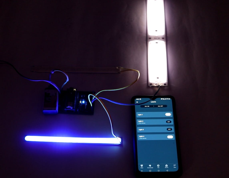
For the demo purposes, we will be connecting some LED strips but you can connect whatever you want to this circuit. So let’s take a look at the circuit.
The CircuitThe Altium designer environment has loaded. This is where we will be connecting the input voltage. A 7805 regulator is linked to the input power. The 7805 can take an input voltage of 7–32V and regulate it down to a constant 5V DC supply. LEDs serve as indicators at key spots to make troubleshooting easier.
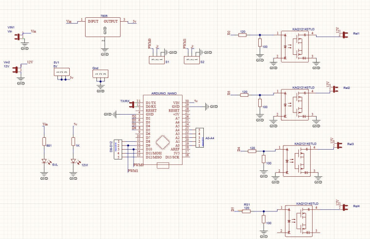
Here I will be using an Arduino Nano with WiFi connectivity for this project. This board operating voltage is 3.3V so you have to keep in mind that, the maximum voltage that can be sent to Arduino GPIO pins is 3.3V, and make sure that you will not be connecting any voltage greater than 3.3V to Arduino GPIO as it may damage the board.
Here, If you take a closer look, you should be able to see two voltage inputs right? The Arduino and other onboard components can be powered from one voltage input, while the electronic devices attached to the relay can be powered from the other voltage input.
The relays are wired to four different Arduino GPIO pins. Relays are circuits or elements that can open and close switches in an electrical circuit. In this case, I’ll be making use of a Solid State Relay (SSR), a special kind of relay that doesn’t require any sort of mechanical trigger.
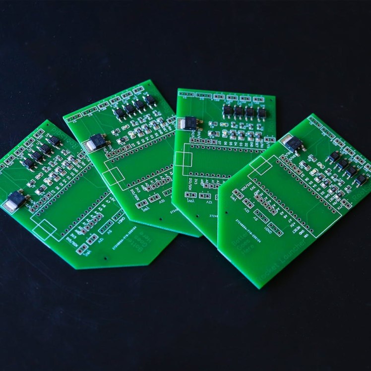
I ordered my PCBs from PCBWay. PCBWay is a PCB manufacturer specializing in PCB prototyping, low-volume production, and neat and tidy PCB Assembly. To order your PCBs from PCB way, Go to the PCBWay website and fill in the basic board details in the instant order form.
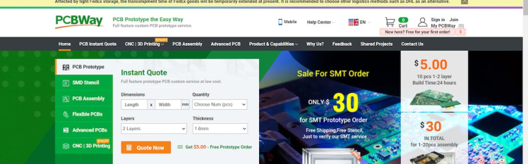
And in the next screen, you can completely customize your PCB. You can change the thickness, change the solder mask color as well as the silkscreen color, materials used, you can customize it in every way possible. Corresponding prices will be updated here in real-time. In PCBWay, you can even manufacture your PCBs with TG 150-160 for the same prices as that of TG 130-140 which means your PCB will be able to operate at high temperatures without any damage.
On the next screen, you should be able to upload your Gerber file and submit it for review. Once the review is completed, all that is left is to add to the cart, make the payment, and wait for your PCBs to arrive.
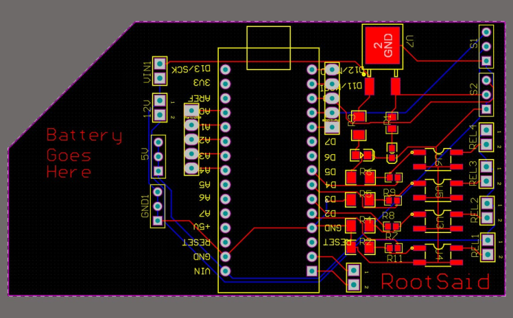
Once you get all the components and the PCB, it’s time for you to solder them together. Solder all the components onto the board and make sure to check the polarity of the components. After soldering the PCB looks like this. And this is it. This one is small and I think it will fit nicely on top of the glove
Let’s move on to the programmatic details now. In this instance, I’ll be utilizing Arduino IoT Cloud to write the board’s code.
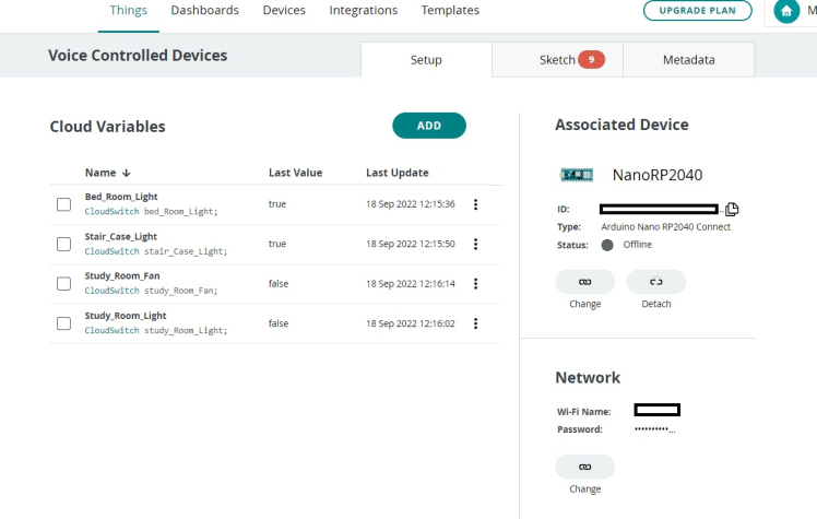
Go to things, then pick the “make a thing” tab. Everything pertinent to your project is listed here. This is where you can view all of the information related to your project in one place, including the circuit board, variables, network, sketch, etc. The first step is to name the project. The complete setup for the project can be seen below.
Now let’s take a look at the code. Arduino IoT cloud is helpful because after you’ve set up your thing and all the variables, it will automatically build a skeleton code that includes all the variables and critical function that is needed to run the code. More variables and operations need only be added.
Now I will be removing all unnecessary comments so that it will look, neet. And here are our final code guys now let’s take a deeper look into it.
#include "thingProperties.h"

void setup() {
  Serial.begin(9600);
  delay(1500);
  initProperties();
  ArduinoCloud.begin(ArduinoIoTPreferredConnection);
  setDebugMessageLevel(2);
  ArduinoCloud.printDebugInfo();
}

void loop() {
  ArduinoCloud.update();

}


void onBedRoomLightChange()  {
  if (bed_Room_Light == 1)
  {
    digitalWrite(5, HIGH);
    Serial.println(" Bed Room Light ON! ");
  }
  else
  {
    digitalWrite(5, LOW);
    Serial.println(" Bed Room Light OFF! ");
  }
}

void onStudyRoomLightChange()  {
  if (study_Room_Light == 1)
  {
    digitalWrite(5, HIGH);
    Serial.println(" Study Room Light ON! ");
  }
  else
  {
    digitalWrite(5, LOW);
    Serial.println(" Study Room Light OFF! ");
  }
}


void onStudyRoomFanChange()  {
  if (bed_Room_Light == 1)
  {
    digitalWrite(5, HIGH);
    Serial.println(" Study Room Fan ON! ");
  }
  else
  {
    digitalWrite(5, LOW);
    Serial.println(" Study Room Fan OFF! ");
  }
}


void onStairCaseLightChange()  {
  if (stair_Case_Light == 1)
  {
    digitalWrite(5, HIGH);
    Serial.println(" Stair Case Light ON! ");
  }
  else
  {
    digitalWrite(5, LOW);
    Serial.println(" Stair Case Light OFF! ");
  }
}
In the setup function, we will initialize the serial communication, and communication with the Arduino cloud set the pin mode, and then prepare the carrier to run the remaining code.
For each of these four variables, the associated function will be executed whenever there is a change. The corresponding function will be executed whenever one of the values changes. For instance, the onlight1Change function will be executed whenever the light1 variable is updated. Turns on light 1 if its value is 1, otherwise turn it off. It’s the same with lights 2 and 3 and 4. Yes, I think you’ll agree that was dead easy.
How do we alter this variable now? We’ll use Alexa to flip the switch, you’re right about that. You can now upload your code to your board because it is complete.
Configuring AlexaNow, take out your smartphone and launch Alexa App. Go ahead and install the Arduino Skill for Alexa and log in with your credentials.
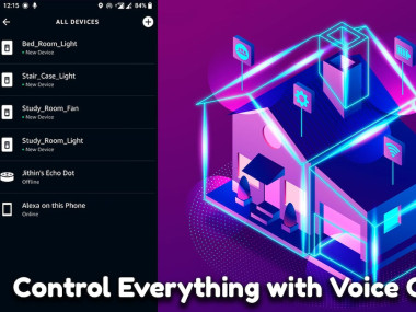
Now tap on discover devices. It will start scanning for any IoT-based Alexa-supported devices. Once the scan is completed, it will show you all the variables we created earlier. Setup those devices and click done. That’s it, guys.
TestingThe devices should now respond to voice commands issued through Alexa. The Alexa app on your phone, as well as Echo Dot and other Amazon devices, can be used to communicate with Alexa and command these devices.
Please subscribe to our channel if you enjoyed this build and are interested in seeing more incredible DIY builds. Let’s begin work on the project right away.
Schematics, diagrams and documents
Code
Credits
Related products


Leave your feedback...