
Control Dc Motor With Encoder Optical Sensor Module Fc-03

About the project
In Visuino, at the bottom click on the "Build" Tab, make sure the correct port is selected, then click on the "Compile/Build and Upload" but
Items used in this project
Hardware components

Story
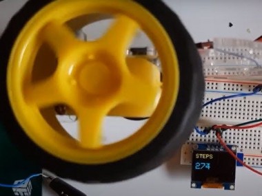
In this tutorial we will learn how to count Optical encoder interrupts using a DC motor, OLED display and Visuino.
Watch the video!
Step 1: What You Will Need
1 / 7
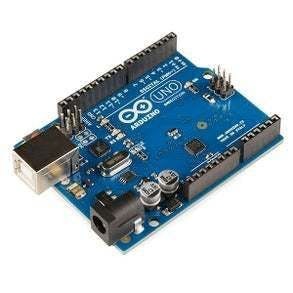


- Arduino UNO (or any other Arduino)
- Optical Coupling Sensor Module FC-03
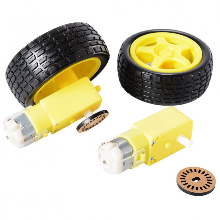
- DC motor
- Encoder wheel (with holes) that you attach on the DC motor
- OLED Display
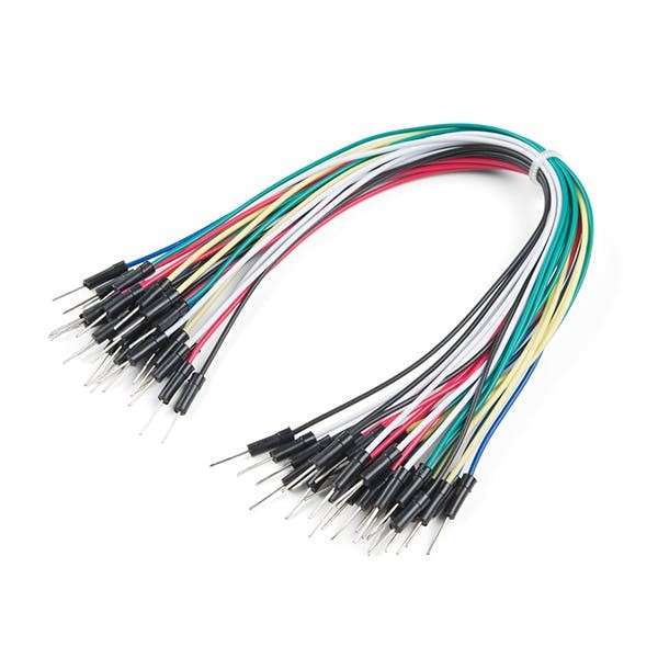
- Jumper wires
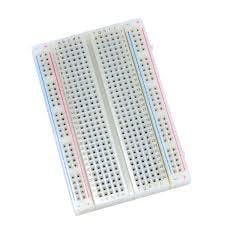
- Breadboard
- Visuino program: Download Visuino
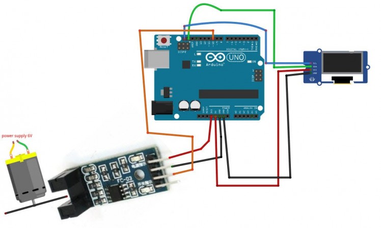
- Connect OLED Display pin [VCC] to Arduino pin [5V]
- Connect OLED Display pin [GND] to Arduino pin [GND]
- Connect OLED Display pin [SCL] to Arduino pin [5V]
- Connect Encoder FC-03 pin [VCC] to Arduino pin [5V]
- Connect Encoder FC-03 pin [GND] to Arduino pin [GND]
- Connect Encoder FC-03 pin [D0] to Arduino digital pin [10]
- Connect power supply [3-6V] to the DC motor
1 / 2
To start programming the Arduino, you will need to have the Arduino IDE installed from here: https://www.arduino.cc/.
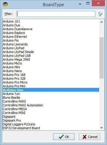
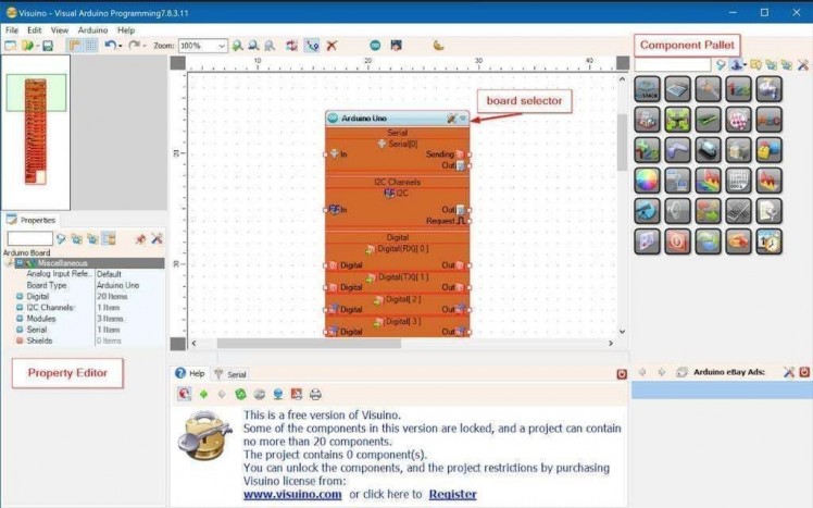
Please be aware that there are some critical bugs in Arduino IDE 1.6.6. Make sure that you install 1.6.7 or higher, otherwise this tutorial will not work! If you have not done follow the steps in this tutorial to setup the Arduino IDE to program Arduino UNO! The Visuino: https://www.visuino.eu also needs to be installed. Start Visuino as shown in the first picture Click on the "Tools" button on the Arduino component (Picture 1) in Visuino When the dialog appears, select "Arduino UNO" as shown on Picture 2
Step 4: In Visuino ADD and Set Components
1 / 6
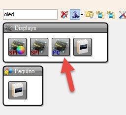
- Add "SSD1306/SH1106 OLED Display (I2C)" component
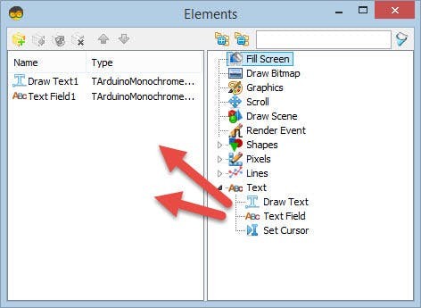
Double click on the "DisplayOLED1" component and:
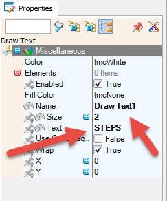
in the Elements window drag "Draw Text" to the left side, On the Left side select Draw Text1 and in the properties window set size to 2 and text: STEPS
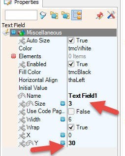
in the Elements window drag "Text Field" to the left side On the Left side select TextField1 and in the properties window set size to 3 and Y:30Close the elements window
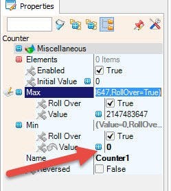
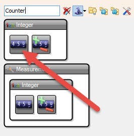
- Add "Counter" component
Select Counter1 component and in the properties window set Min>Value to 0
Step 5: In Visuino Connect Components
1 / 3
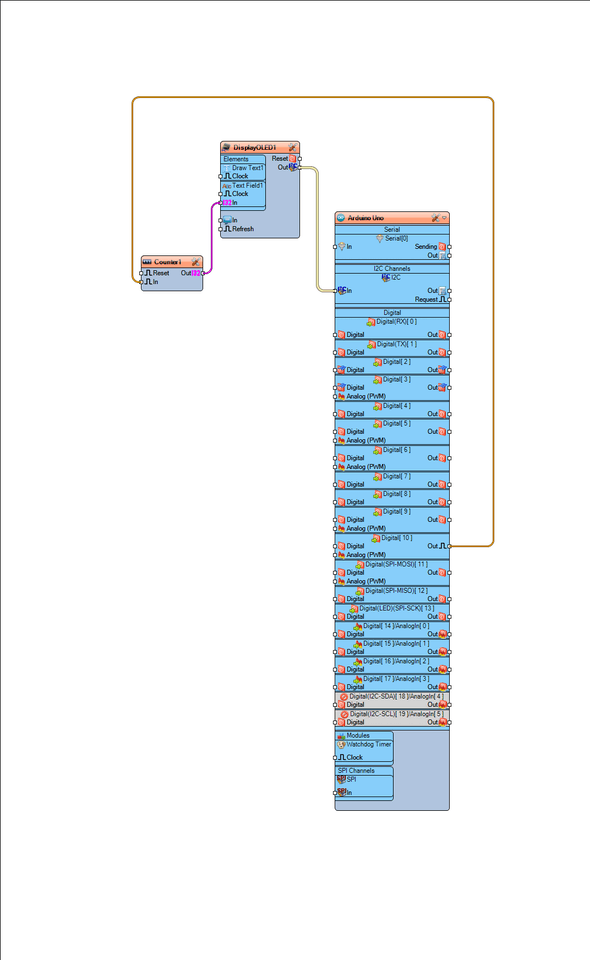
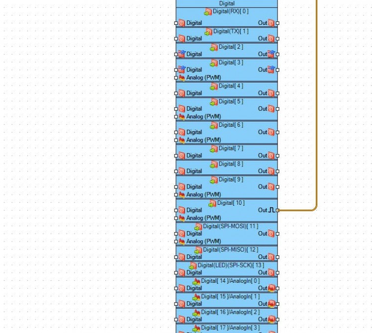
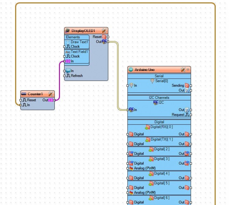
- Connect Arduino board digital pin [10] to Counter1 pin [In]
- Connect Counter1 pin [Out] to DisplayOLED1>TextField1 pin[In]
- Connect DisplayOLED1 I2C pin[Out] to Arduino board pin I2C [In]
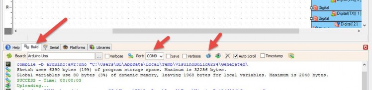
In Visuino, at the bottom click on the "Build" Tab, make sure the correct port is selected, then click on the "Compile/Build and Upload" button.
Step 7: PlayIf you power the Arduino UNO module, and connect the DC motor to the power supply to run it the OLED Display should will show the number of interuptions (count).
Congratulations! You have completed your project with Visuino. Also attached is the Visuino project, that I created for this tutorial, you can download it and open it in Visuino: https://www.visuino.eu
Schematics, diagrams and documents
Code
Credits
Related products


Leave your feedback...