
Automatic Garden Waterer | 3d Printed | Arduino

Made by DIY-Machines / 3D Printing / Garden / Home Automation / Robotics / Sustainability
About the project
I'm a keen gardener but watering your plants by hand during dry spells takes some time, and when your away from home they suffer. This simple project takes care of watering them automatically and can be combined with sprinklers, drip irrigation or watering trays.
Project info
Difficulty: Easy
Platforms: Arduino
Estimated time: 1 hour
License: Creative Commons Attribution-NonCommercial CC BY-NC version 4.0 or later (CC BY-NC 4+)
Items used in this project
Hardware components

View all
Story
Step 1: Video
If you prefer to follow along with a video then I have made one which you can watch, otherwise read on...
Step 2: Bill of Materials
You'll need a few things to build one of your own:
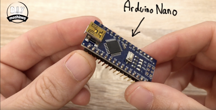
■ Elegoo Arduino Nano (x1): https://geni.us/ArduinoNanoV3
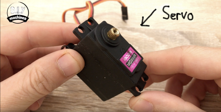
■ Servo (x1): https://geni.us/Servo
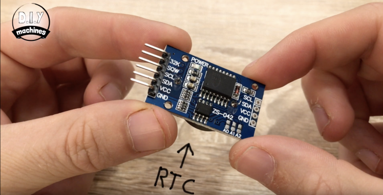
■ Real time clock (x1): https://geni.us/DS3231-RTC
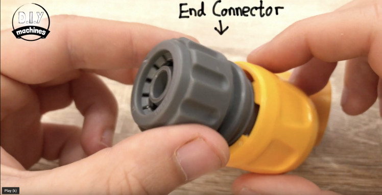
■ Hoselock compatible connector (x2): https://geni.us/hose-connectors
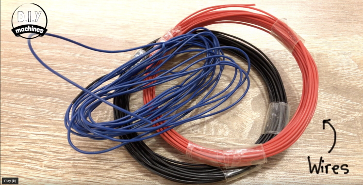
■ Wire: https://geni.us/22AWGWire
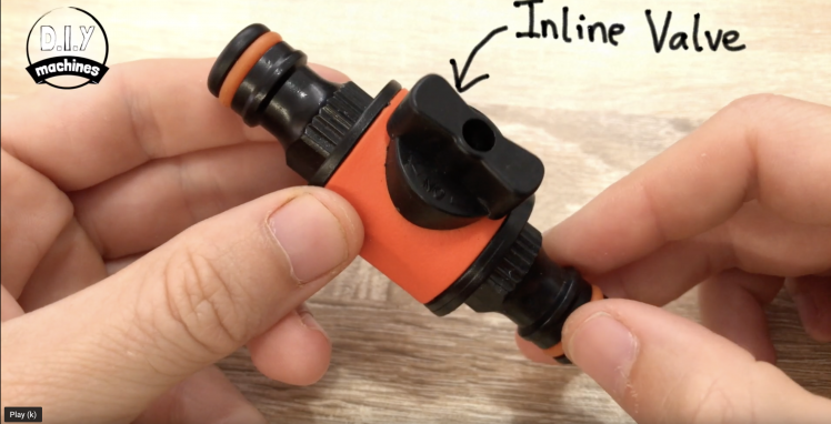
■ Hoselock compatible inline valve (x1): https://geni.us/hozelock-valve
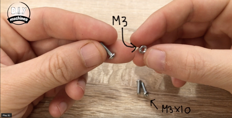
■ Nuts and Bolts - M3 x 10 (x3): http://geni.us/NutsAndBolts
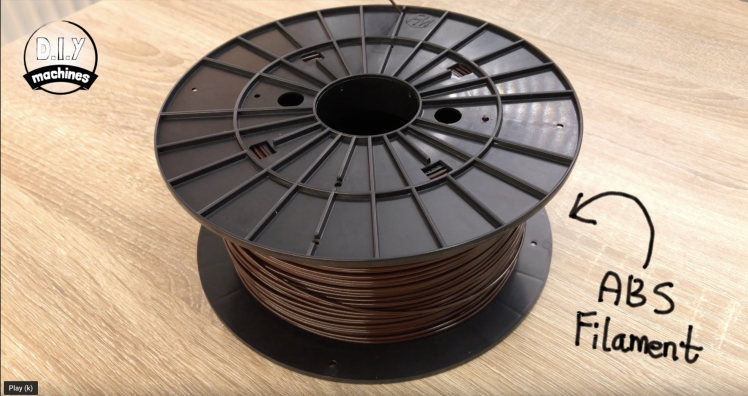
■ ABS Filament: https://geni.us/ABS-Filament
■ Long Usb cable (x1) https://geni.us/LomgUSBMiniB
■ USB wall plug (x1) https://geni.us/USBWallPlug
If you would prefer to use PLA filament I have good success with this one:
■ PLA Filament: https://geni.us/PLAFilament
Step 3: 3D Printed Parts
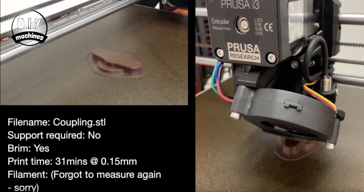
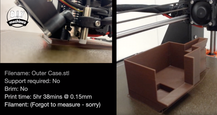
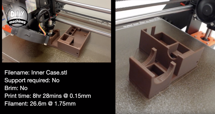
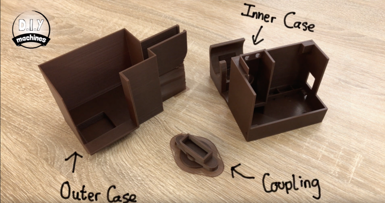
There are three printable parts to this project. The inner and outer case and 'the coupling'.
You can download the 3D models here: https://www.thingiverse.com/thing:3875075
I have printed all of my parts using ABS plastic. You could use PLA or PETG but just know that PLA is the most likely to degrade in outdoor conditions or inside a greenhouse. In the images are the three 3D prints I did as well as the setting that I used for each.
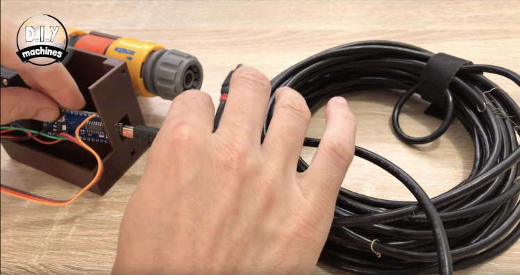
Step 4: Connect the Servo
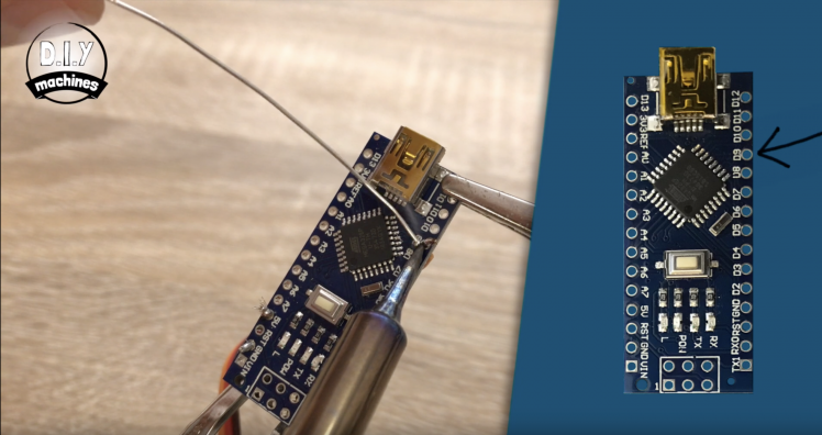
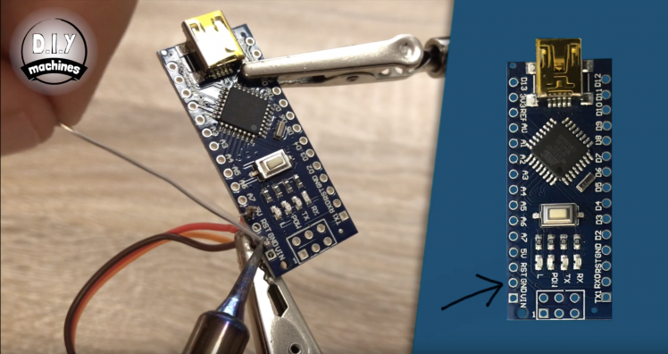
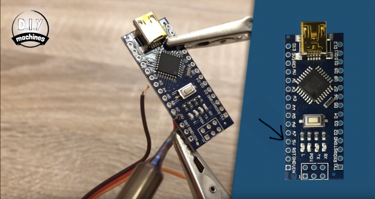

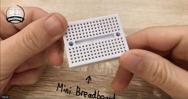
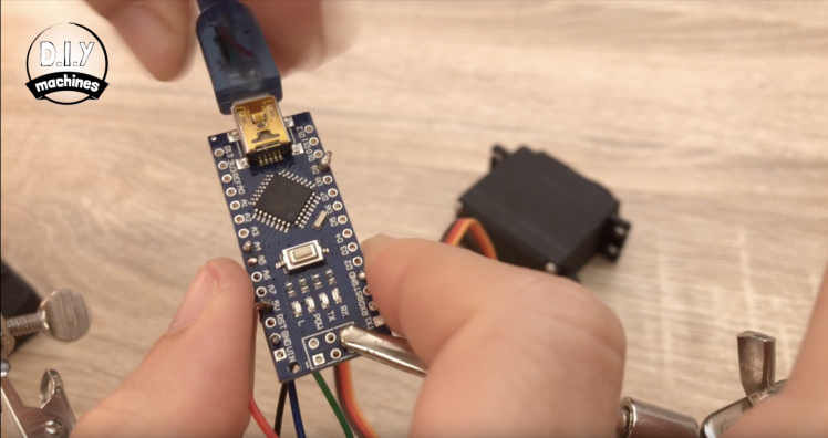
I'm going to be soldering all of my connections in this project as I will be permanently installing this into my garden. If you prefer you can use jumpers and a breadboard to make the same connections as I have with the one in the photo.
There is a circuit diagram available here if you prefer them: https://diymachines.co.uk/projects/automatic-arduino-based-garden-waterer.html
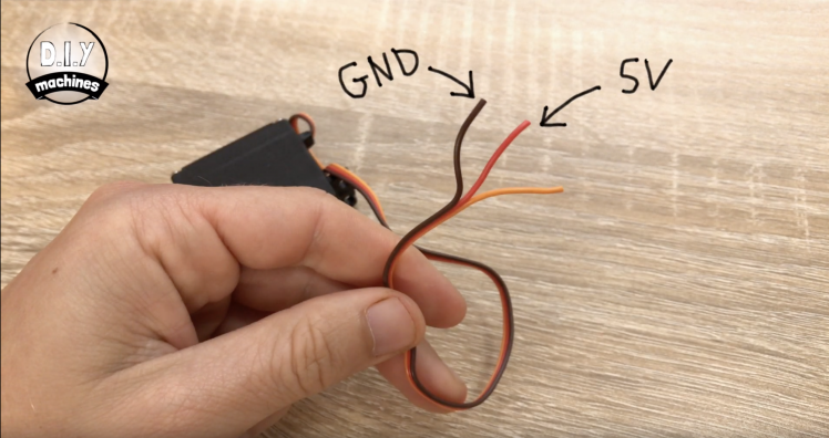
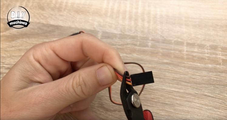
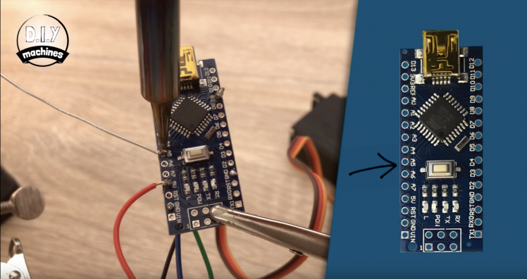
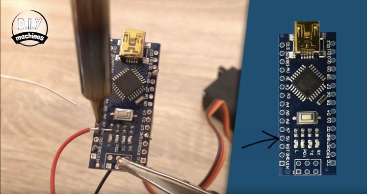
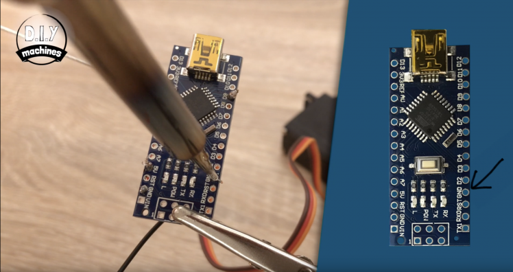
First we can strip the plug of the end of the servo wire and solder this directly to the nano. There are three wires on mine, the red and brown wires are attached to the power and ground so I will attach these to the Arduino's 5V and ground connections. This leaves the orange wire which is our signal wire. This needs to be connected to digital 9 on the Arduino.
Step 5: Connect RTC
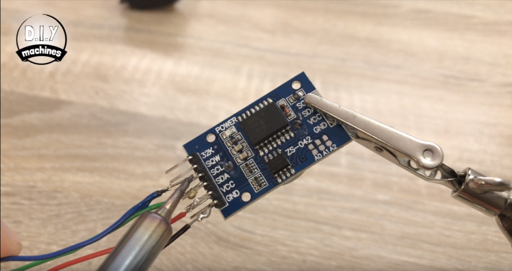
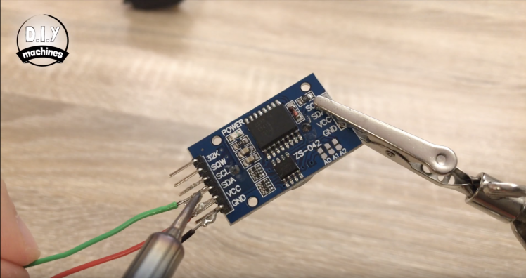
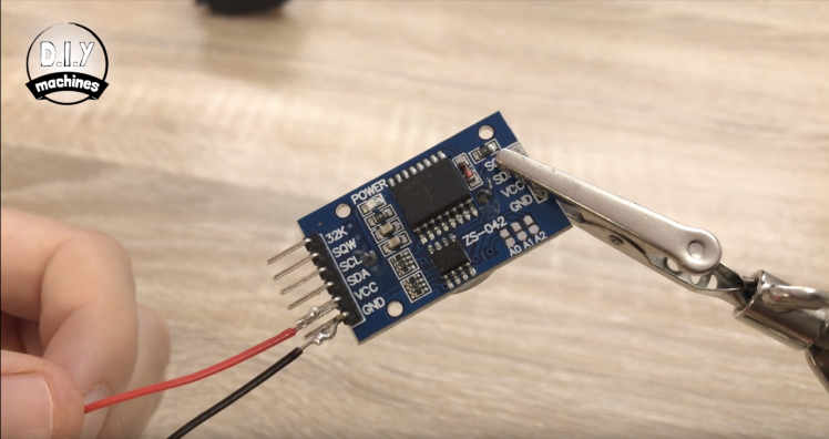
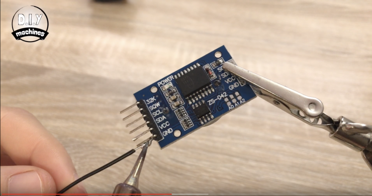
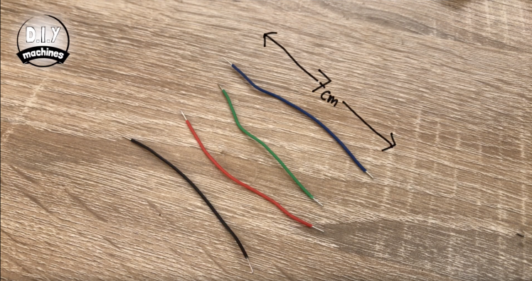
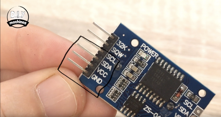
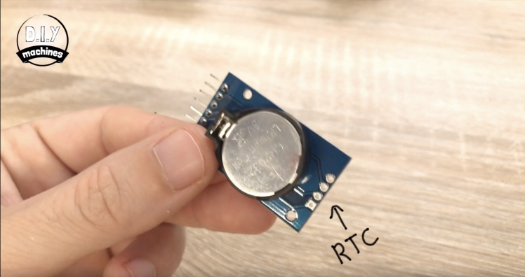
Now we can turn to the Real Time Clock or 'RTC' as it is often shortened too. We will be using four pins. You will need to prepare four 7cm long lengths of wire for this.
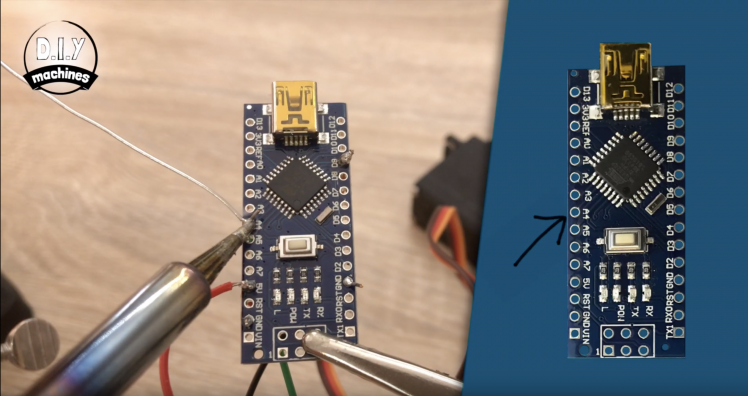
As before the ground lead is connected to ground and VCC to same 5V power supply the servo was just connected to. The SDA pin connects to A4 on the Arduino and SCL to A5.
Step 6: Uploading and Customising the Code
Use a USB cable to connect it to your PC and open the Arduino IDE.
You can download the Arduino IDE here: https://www.arduino.cc/en/main/software
This project uses the handy DS3231 Simple library:- https://github.com/sleemanj/DS3231_Simple Please follow the instruction on installing this provided on the libraries page
And the code for the project can be found here: https://diymachines.co.uk/projects/automatic-ardu...
Before you upload the project main code you need to set the time on your DS3231. Once you have connected it as shown and have installed the DS3231_Simple library (see above) go to 'File' >> 'Examples' >> 'DS3231_Simple' >> 'Z1_TimeAndDate' >> 'SetDateTime' and follow the instructions in the example to set the date and time on your RTC
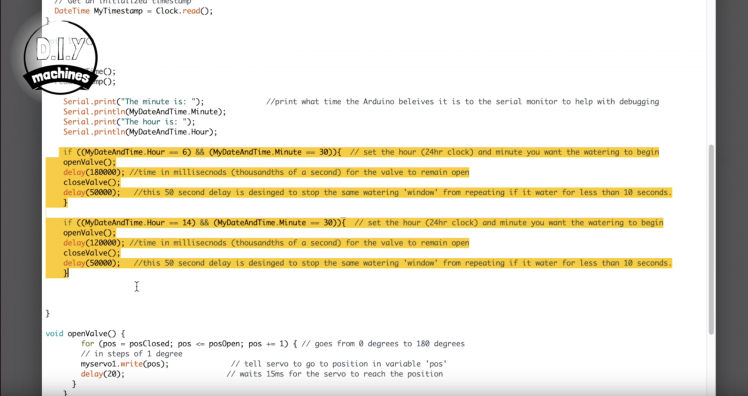
In the main loop of the code are two IF statements which check the time and then initiate the watering sequence for a specified amount of time. The conditional check of the IF statements checks to see if the value of the hours and minutes from the clock match what we have set here. If they both match then the 'Open Valve' function runs, followed by a delay.
This delay (set in thousandths of a second) determines for how long the water is allowed to flow through the hose to your plants. You can have as many of the statements in the main loop of the code as you need.Just copy and paste them whilst updating the conditions of the IF statement and duration of watering (the delay between opening and closing the valve).
Step 7: Fit the Valve

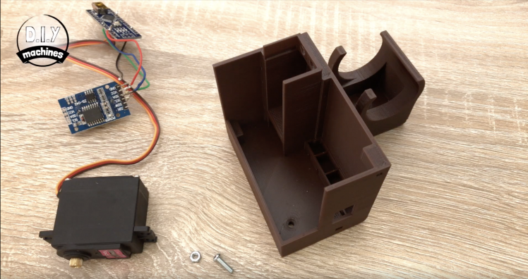
Once you have finished programming your watering schedule we can disconnect it from the computer and begin to complete the assembly.
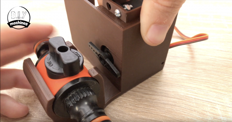
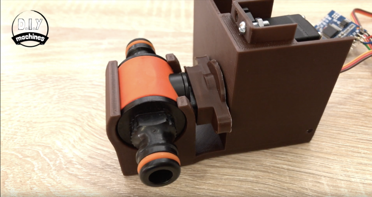
Use one of the M3 bolts and nut to secure the servo into position as shown in the photo. We only need to secure one of the holes to hold it sufficiently.
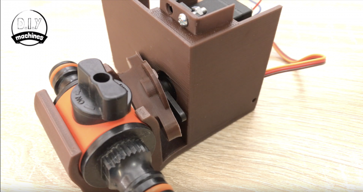
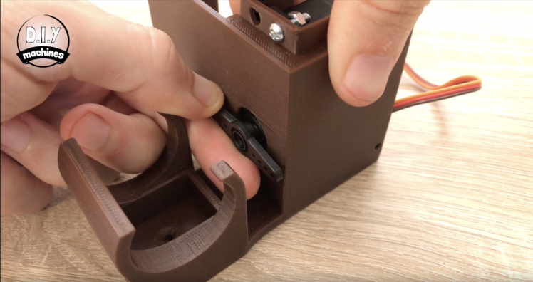
The servo should have come with an assortment of arms that fit to it. We want to fit the straight armed one. When we turn the circuit off after uploading the code the servo should have been left in the valve closed position. So when we fit the arm you want it to be vertical.
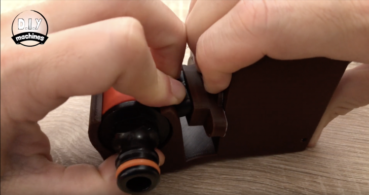
Now rotate it 90 degrees anti-clockwise until it is horizontal. Slide in the inline valve and fit the coupler we printed onto the servo arm. The next bit does require quite a bit of force but you need to rotate the valve towards the coupling whilst pulling it away from the servo. It will take force to pop it into place, but we only need to do this once.
Step 8: Connect the Cable and Attach the Cover
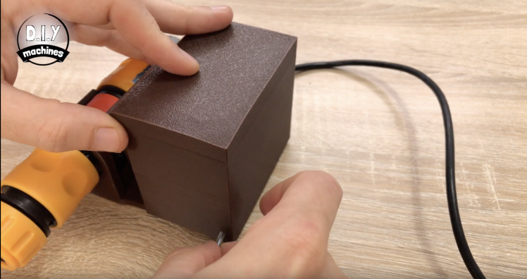
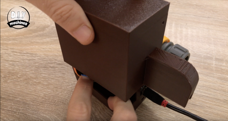
I'm going to use a 10m long USB lead to connect it to my outdoor power socket to power mine. Let's connect the Arduino end of the cable now and finish of the enclosure.
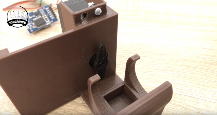
I've soldered my connections directly to the board so I'm just going to squeeze my electronics into place inside the enclosure. If yours is on a breadboard you can use the self adhesive backing to hold it in place on the ledge provided.
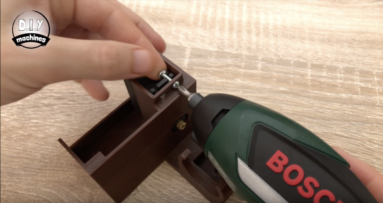
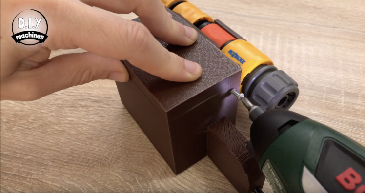
There are two screws that need to be inserted to complete the housing. This should keep it fairly weather resistant whilst kept upright. If you wanted to secure it to a plank or floor there are two screw holes (one underneath the inline valve and one inside the enclosure - you would need to secure these to something before proceeding with the assembly as they cannot be accessed afterwards.
Step 9: Connect It Outside
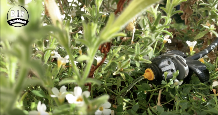
Let's now take our project to the garden.
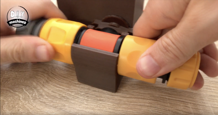
I will install the project between my tap and hanging baskets. Earlier I installed a drip irrigation kit by Hoselock to each of my hanging baskets. This is the one I've been using with good success: https://geni.us/Hozelock-Irrigation
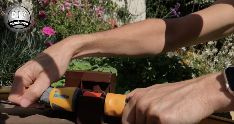
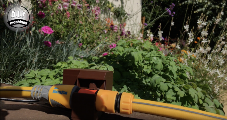
Now we attach this to our hosepipe between the tap and irrigation kit using the two of the quick fit connectors.
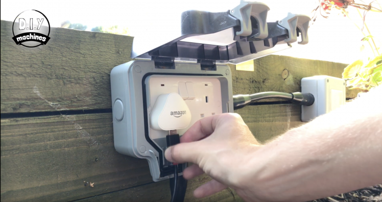
I powered mine with the long USB cable connected to an outdoor socket.
Step 10: Project Complete!

And that's it, my hanging baskets will now take good care of themselves until early Winter. :)
Thanks for taking a look at my tutorial. I hope you've enjoyed this project. If you have please think about checking out some of my other projects, don't forget to subscribe to DIY machines on here and YouTube and share this project with anyone you know who might like to build one of their own.
Otherwise until next time chow for now!
Subscribe to my Youtube channel: https://www.youtube.com/channel/UC3jc4X-kEq-dEDYhQ8QoYnQ?sub_confirmation=1
Support me on Patreon: : https://www.patreon.com/diymachines
FACEBOOK: https://www.facebook.com/diymachines/
Schematics, diagrams and documents
CAD, enclosures and custom parts
Code
Credits
Related products


Leave your feedback...