
Autobill

Made by CodersCafeTech / Artificial intelligence / Displays / Home Automation / Productivity / IoT
About the project
AI-powered autonomous checkout system for retail stores.
Project info
Difficulty: Difficult
Platforms: Microsoft, Raspberry Pi, SparkFun, Edge Impulse, Seeed
Estimated time: 5 days
License: Apache License 2.0 (Apache-2.0)
Items used in this project
Hardware components

View all
Hand tools and fabrication machines
Story
AutoBill is an AI-powered autonomous checkout system for retail stores, that combines the power of computer vision and machine learning to provide an amazing shopping experience. AutoBill provides a faster checkout shopping experience to minimize human interactions in the store to keep shoppers and employees safer during the pandemic.
AutoBill uses computer vision and machine learning to visually detect and instantly identify the items placed and the weight sensor measure the weights of the things placed on the counter-top. Once the items are identified, things are automatically added to the cart and the bill is generated instantaneously. QR code for payment is generated and users can pay the bill by scanning the QR code
Features- AI-powered
- Instant checkout
- contact-free checkout
- Easy deployment
So Let's dive in.
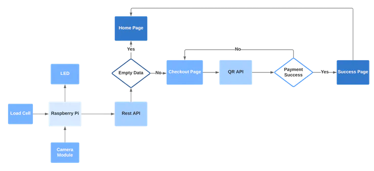
Work Flow
Let's have a look at the logical flow of AutoBill.
Object detection

Edge Impulse is one of the leading development platforms for machine learning on edge devices, free for developers and trusted by enterprises. Here we are using machine learning to build a system that can recognize the products available in the shops. Then we deploy the system on the Raspberry Pi 3B.
Data acquisition
To make the machine learning model it's important to have a lot of images of the products. When training the model, these product images are used to let the model distinguish between them. Make sure you have a wide variety of angles and zoom levels of the products which are available in the shops. For the data acquisition, you can capture data from any device or development board, or upload your existing datasets. So here we are uploading our existing datasets.
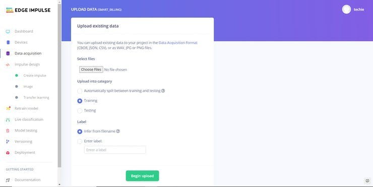
For uploading, just moves on to the Data acquisition tab and just choose a file. Then label it and upload it to the training section. The Edge Impulse will only accept either JPG or PNG image files. If you have any other format, just convert it to JPG or PNG format with the online converters.
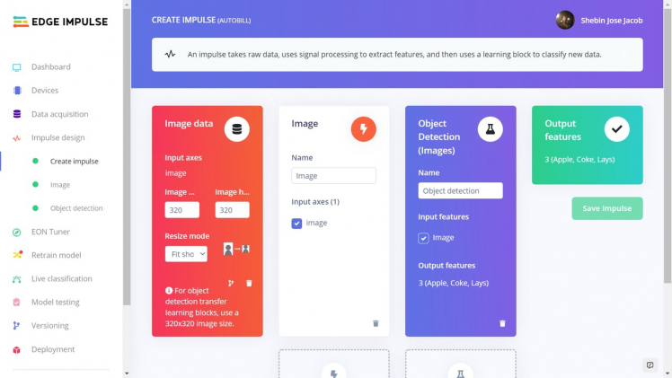
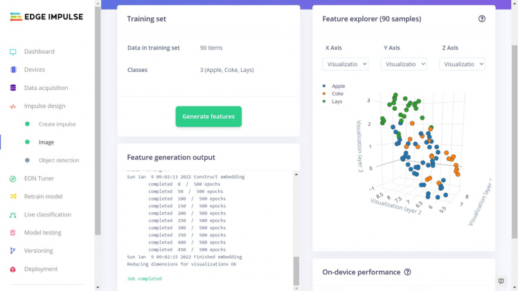
So we uploaded all the data with the four different labels such as Apple Lays, and Coke. So the system will only identify these objects when checking out. If you want to recognize any other objects other than these you need to upload the dataset of them. Here we uploaded around 40 images for each object. Neural networks need to learn patterns in data sets, and the more data the better
Labelling Data
The labeling queue shows you all the unlabeled data in your dataset. Labeling objects is as easy as dragging a box around the object, and entering a label. To make the life a bit easier we try to automate this process by running an object tracking algorithm in the background. If you have the same object in multiple photos we thus can move the boxes for you and you just need to confirm the new box. After dragging the boxes, click Save labels and repeat this until your whole dataset is labeled.

Designing an Impulse
With the training set in place, you can design an impulse. An impulse takes the raw data, adjusts the image size, uses a preprocessing block to manipulate the image, and then uses a learning block to classify new data. Preprocessing blocks always return the same values for the same input (e.g. convert a color image into a grayscale one), while learning blocks learn from past experiences.
For this system, we'll use the 'Images' preprocessing block. This block takes in the color image, optionally makes the image grayscale, and then turns the data into a features array. Then we'll use a 'Transfer Learning' learning block, which takes all the images in and learns to distinguish between the two ('coffee', 'lamp') classes.
In the studio go to Create impulse, set the image width and image height to 96, the 'resize mode' to Fit shortest axis, and add the 'Images' and 'Object Detection (Images)' blocks. Then click Save impulse.
Then in the image tab, you can see the raw and processed features of every image. You can use the options to switch between 'RGB' and 'Grayscale' mode, but for now, leave the color depth on 'RGB' and click Save parameters.
This will send you to the Feature generation screen. In here you'll:
- Resize all the data.
- Apply the processing block on all this data.
- Create a 3D visualization of your complete dataset.
Click Generate features to start the process.
Afterward the 'Feature explorer' will load. This is a plot of all the data in your dataset. Because images have a lot of dimensions (here: 96x96x3=27648 features) we run a process called 'dimensionality reduction' on the dataset before visualizing this. Here the 27648 features are compressed down to just 3, and then clustered based on similarity. Even though we have little data you can already see the clusters forming and can click on the dots to see which image belongs to which dot.
With all data processed it's time to start training a neural network. Neural networks are a set of algorithms, modeled loosely after the human brain, that are designed to recognize patterns. The network that we're training here will take the image data as an input, and try to map this to one of the three classes.
It's very hard to build a good working computer vision model from scratch, as you need a wide variety of input data to make the model generalize well, and training such models can take days on a GPU. To make this easier and faster we are using transfer learning. This lets you piggyback on a well-trained model, only retraining the upper layers of a neural network, leading to much more reliable models that train in a fraction of the time and work with substantially smaller datasets.
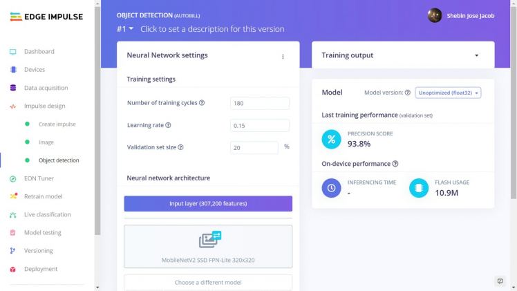
To configure the transfer learning model, click Object detection in the menu on the left. Here you can select the base model (the one selected by default will work, but you can change this based on your size requirements), and set the rate at which the network learns.
Leave all settings as-it is, and click Start training. After the model is done you'll see accuracy numbers below the training output. We have now trained our model.
With the model trained let's try it out on some test data. When collecting the data we split the data up between training and a testing dataset. The model was trained only on the training data, and thus we can use the data in the testing dataset to validate how well the model will work in the real world. This will help us ensure the model has not learned to overfit the training data, which is a common occurrence.
To validate your model, go to Model testing and select Classify all. Here we hit 93.75% precision, which is great for a model with so little data.
To see classification in detail, click the three dots next to an item, and select Show classification. This brings you to the Live classification screen with much more details on the file (you can also capture new data directly from your development board from here). This screen can help you determine why items were misclassified.
With the impulse designed, trained, and verified you can deploy this model back to your device. This makes the model run without an internet connection, minimizes latency, and runs with minimum power consumption. Edge Impulse can package up the complete impulse - including the preprocessing steps, neural network weights, and classification code - in a single C++ library or model file that you can include in your embedded software.
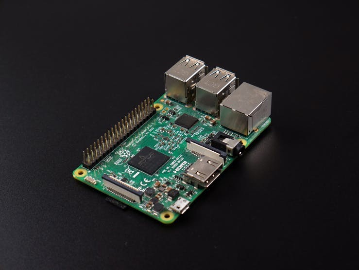
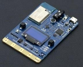
RASPBERRY PI 3B
The Raspberry Pi 3B is the powerful development of the extremely successful credit card-sized computer system. The brain of the device is Raspberry Pi. All major processes are carried out by this device.
If you don't know how to set up the Pi just go here.
To set this device up in Edge Impulse, run the following commands:
curl -sL https://deb.nodesource.com/setup_12.x | sudo bash -
sudo apt install -y gcc g++ make build-essential nodejs sox gstreamer1.0-tools gstreamer1.0-plugins-good gstreamer1.0-plugins-base gstreamer1.0-plugins-base-apps
npm config set user root && sudo npm install edge-impulse-linux -g --unsafe-perm
If you have a Raspberry Pi Camera Module, you also need to activate it first. Run the following command:
sudo raspi-configUse the cursor keys to select and open Interfacing Options, and then select Camera and follow the prompt to enable the camera. Then reboot the Raspberry.
With all software set up, connect your camera to Raspberry Pi and run.
edge-impulse-linuxThis will start a wizard which will ask you to log in and choose an Edge Impulse project. If you want to switch projects run the command with --clean.
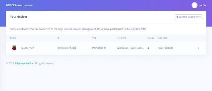
That's all! Your device is now connected to Edge Impulse. To verify this, go to your Edge Impulse project, and click Devices. The device will be listed here.
To run your impulse locally, just connect to your Raspberry Pi again, and run.
edge-impulse-linux-runner.This will automatically compile your model with full hardware acceleration, download the model to your Raspberry Pi, and then start classifying.
Here we are using the Linux Python SDK for integrating the model with the system. For working with the Python SDK you need to have a recent version of the Python(>=3.7)
For installing the SDK for the Raspberry pi, you need to run the following commands.
sudo apt-get install libatlas-base-dev libportaudio0 libportaudio2 libportaudiocpp0 portaudio19-dev
pip3 install edge_impulse_linux -i https://pypi.python.org/simple
To classify data, you'll need a model file.We have already trained our model. This model file contains all signal processing code, classical ML algorithms, and neural networks - and typically contains hardware optimizations to run as fast as possible. To download the model file run the below command.
edge-impulse-linux-runner --download modelfile.eimThis downloads the file into modelfile.eim.
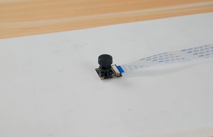
Camera Module
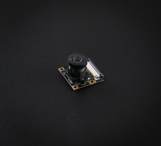
Here I am using the REES52 5 Megapixel 160° degrees Wide Angle Fish-Eye Camera for the object detection. Due to its high viewing angle, it can cover more area than the normal camera module. The main feature of this camera module is
- Omnivision 5647 sensor in a fixed-focus module.
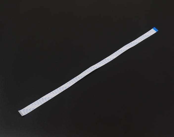
- The module attaches to Raspberry Pi, by way of a 15 Pin Ribbon Cable, to the dedicated 15-pin MIPI Camera Serial Interface (CSI).
- The CSI bus is capable of extremely high data rates, and it exclusively carries pixel data to the BCM2835 processor.
- The sensor itself has a native resolution of 5 megapixels and has a fixed focus lens onboard.
- The camera supports 1080 p @ 30 fps, 720 p @ 60 fps, and 640 x480 p 60/90 video recording also it is supported in the latest version of Raspbian, the Raspberry Pi's preferred operating system.
For connecting the camera module to the Raspberry pi, we have used 18'' flex cable. There is considerable distance between the Raspberry Pi and the camera module.
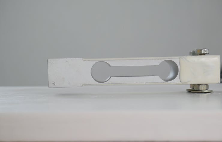
Weight Sensor(Load Cell)

Here we use the Load cell to measure the weight of the objects. The load cell Is a sensor or a transducer that converts a load or force acting on it into an electronic signal. This electronic signal can be a voltage change, current change, or frequency change depending on the type of load cell and circuitry used. There are many different kinds of load cells.
Here we are using a resistive load cell. Resistive load cells work on the principle of piezo-resistivity. When a load/force/stress is applied to the sensor, it changes its resistance. This change in resistance leads to a change in output voltage when an input voltage is applied. The resistive load cell is made by using an elastic member (with a very highly repeatable deflection pattern) to which a number of strain gauges are attached.

Here we are using a load cell which is having four strain gauges that are bonded to the upper and lower surfaces of the load cell.
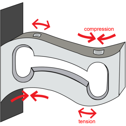
When the load is applied to the body of a resistive load cell, as shown above, the elastic member, deflects as shown and creates a strain at those locations due to the stress applied. As a result, two of the strain gauges are in compression, whereas the other two are in tension.
During a measurement, the weight acts on the load cell’s metal spring element and causes elastic deformation. This strain (positive or negative) is converted into an electrical signal by a strain gauge (SG) installed on the spring element. The simplest type of load cell is a bending beam with a strain gauge. We use the Wheatstone bridge circuit to convert this change in strain/resistance into a voltage that is proportional to the load.
The four strain gauges are configured in a Wheatstone Bridge configuration with four separate resistors connected as shown in what is called a Wheatstone Bridge Network. An excitation voltage – usually 5V is applied to one set of corners and the voltage difference is measured between the other two corners. At equilibrium with no applied load, the voltage output is zero or very close to zero when the four resistors are closely matched in value. That is why it is referred to as a balanced bridge circuit.
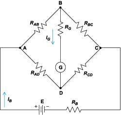
When the metallic member to which the strain gauges are attached, is stressed by the application of a force, the resulting strain – leads to a change in resistance in one (or more) of the resistors. This change in resistance results in a change in output voltage. This small change in output voltage (usually about 20 mv of the total change in response to full load) can be measured and digitized after careful amplification of the small milli-volt level signals to a higher amplitude 0-5V signal.
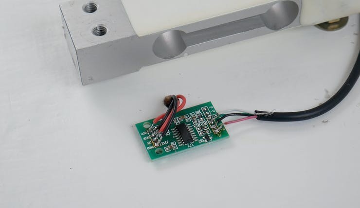
HX711 Break-out board
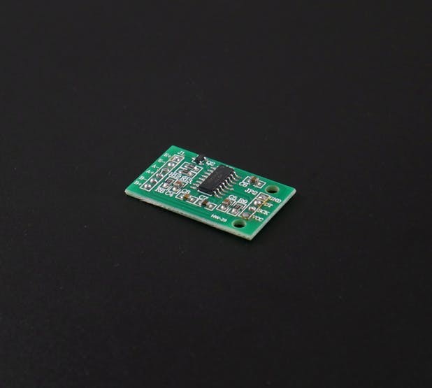
The HX711 module is a Load Cell Amplifier breakout board that allows you to easily read load cells to measure weight. This module uses 24 high-precision A/D converter chips HX711. It is specially designed for the high precision electronic scale design, with two analog input channels, the internal integration of 128 times the programmable gain amplifier. The input circuit can be configured to provide a bridge type pressure bridge (such as pressure, weighing sensor mode), is of high precision, low cost is an ideal sampling front-end module.
HX711 is an IC that allows you to easily integrate load cells into your project. No need for any amplifiers or dual power supply just use this board and you can easily interface it to any micro-controller to measure weight.
The HX711 uses a two-wire interface (Clock and Data) for communication. Compared with other chips, HX711 has added advantages such as high integration, fast response, immunity, and other features improving the total performance and reliability. Finally, it's one of the best choices for electronic enthusiasts. The chip lowers the cost of the electronic scale, at the same time, improving performance and reliability. Its specifications are
- Differential input voltage: ±40mV (Full-scale differential input voltage is ± 40mV)
- Data accuracy: 24 bit (24 bit A / D converter chip.)
- Refresh frequency: 10/80 Hz
- Operating Voltage: 2.7V to 5VDC
- Operating current: <10 mA
- Size: 24x16mm
Calibration
Connect the load cell, HX711 module to the Raspberry pi as per the schematics and run the calibration.py code in raspberry pi. Then you will get the ratio of your own load cell and just put in it your main code. Each load cell ratio would be different on different occasions. Below is my calibration of the load cell.
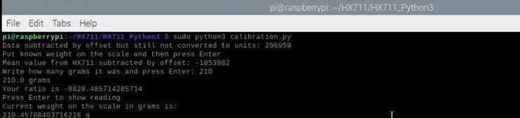
So weighing with my load cell is 90 % accurate. For connecting the load cell with the raspberry pi using the HX711, I have used the pieces of code by Marcel Zak. You can find his repository here .
WS2812B RGB LED Strip
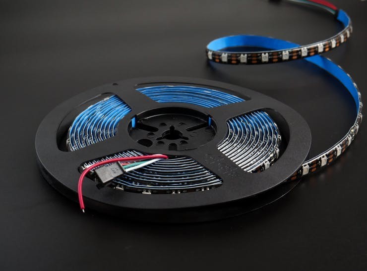
The WS2812B 5V Addressable RGB Waterproof LED Strip is extremely flexible, easy to use and each LED of the strip can be controlled separately by using a microcontroller. Each LED has been equipped with an integrated driver that allows you to control the color and brightness of each LED independently. To light up the commodities in the system we have used this RGB led Strip. The combined LED/driver IC on these strips is the extremely compact WS2812B (essentially an improved WS2811 LED driver integrated directly into a 5050 RGB LED), which enables higher LED densities. WS2812B uses a specialized one-wire control interface and requires strict timing.
Power supply

Here we used a 5V 2A power supply for powering the entire project. We have also used a DC power jack for plugging this adapter.
Dc Power Jack

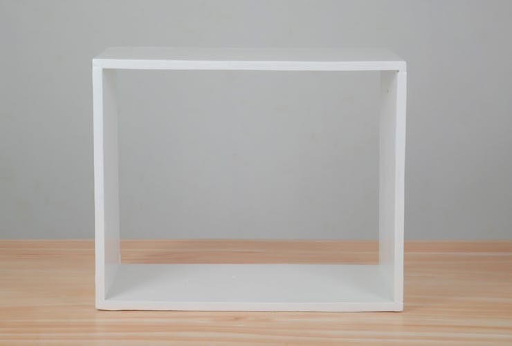
Cabinetry
For making the cabinetry for the system, I have used 4 pieces of plywood with the following dimension.

These plywoods were sanded with 100 grit sandpaper to get a smooth finish. For placing the load cell on the plywood, I made necessary holes in the wood with a drill after properly measuring the spaces for the component. And these plywoods were made to cabinet properly with pieces of the nail.
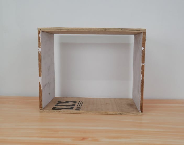
After priming the cabinet, I have used wood fillers to fill the voids present in the cabinet. Finally applied Satin finish paint for the cabinet.
Securing components
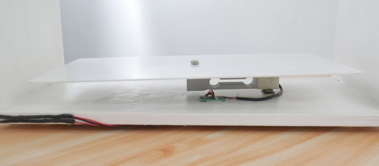
Initially, we attached the load cell on the cabinet with the help of Nuts and bolts.
One end of the load cell should be rigidly connected and another end should be floated in the air, then only we get the proper weight of the object. Then we wired the load cell to the HX711 break-out module by installing it.
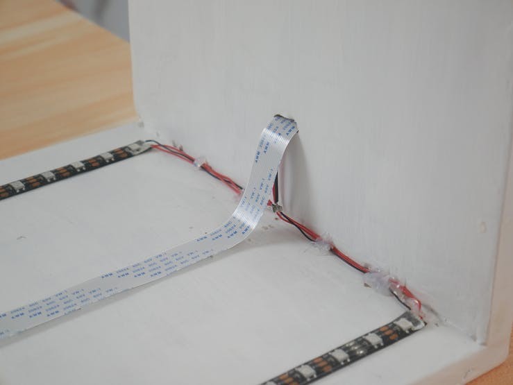
Then we pulled out the wire from the HX711 module through a hole nearby it. Then we installed the camera module at the opposite face of the load cell.
Then we attached the led strip parallel to the camera module.
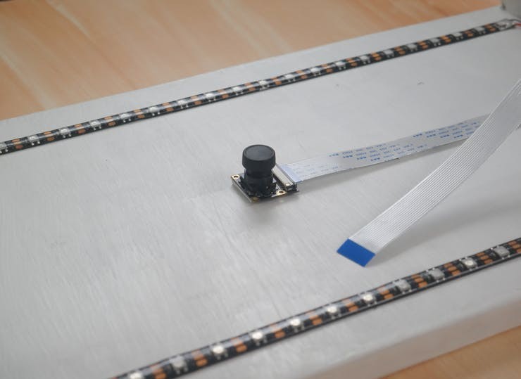
Then these strips were parallelly connected. The flex cable from the camera module and the wire from the strips were pulled out.
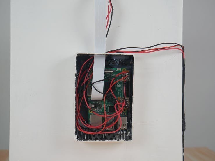
For placing the raspberry pi we have used a white painted black box. It is then screwed to the cabinet.
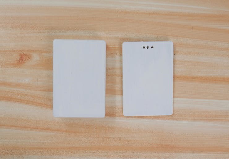
We have also made necessary holes on the white box for connecting components with the raspberry pi.
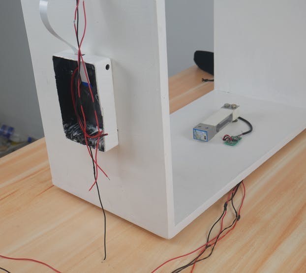
First, we attached the DC power jack into the box.
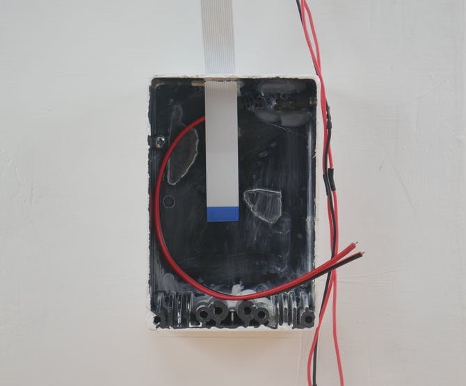
Then we attached the raspberry pi and wired the whole components as per the schematics.
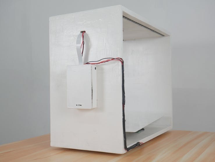
Then we attached the lid. Then the base is fixed. Here we used the base piece as the acrylic sheet cut in proper measurement.
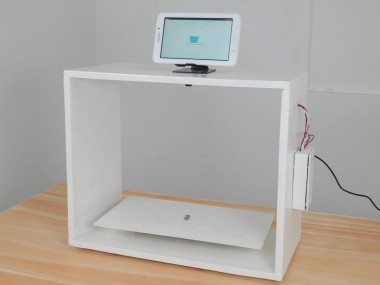
The final will look like this.
Checkout Interface
The checkout interface has two parts,
1. Front-end developed using HTML, JS
2. Backend API developed using NodeJS and Express
1. Front-end developed using HTML, JS
The front-end continuously checks for the changes happening in the back-end API and displays the changes to the user. Once an item is added to the API, the front-end displays as an item added to the cart.
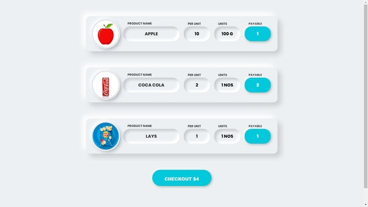
2. Backend API developed using NodeJS and Express
The backend REST API is developed using NodeJS and Express. ExpressJS is one of the most popular HTTP server libraries for Node.js, which ships with very basic functionalities. The backend API keeps the details of the products that are visually identified.
For setting our interface we have used a small tablet which is having a touch interface with a small stand.
What's in Future?- Generate Digital Receipt
- Keeps Transaction History
- Screen Promotions and Offers
- Integration for multiple stores for easy analytics
Schematics, diagrams and documents
CAD, enclosures and custom parts
Code
Credits
Related products


Leave your feedback...