
Home Automation Lamp

Made by bitluni / 3D Printing / Home Automation / Lights / Notifications
About the project
A simple build of a sleeping room lamp which can wake you up with an artificial sunrise.
Project info
Difficulty: Moderate
Platforms: Arduino
Estimated time: 2 days
License: Creative Commons Attribution CC BY version 4.0 or later (CC BY 4+)
Items used in this project
Hardware components


View all
Story
Overview
The main goal of this project is to have a lamp that provides a convenient alarm function simulating a sunrise. The sunrise lasts for about 30 minutes until full brightness and will wake you smoothly during a shallow sleeping phase. Since this project uses RGB LEDs these can be set to any color using a remote.
Requirements
Both the lamp and the remote are using your WiFi and communicate over MQTT. An MQTT server is needed for this to work.
The code which is linked in the repository is written in c++ and can be uploaded using the free Arduino IDE with the ESP8266 extension. Additional libraries needed are Adafruit MQTT, Adafruit NeoPixel and for the LCD remote the 4D systems GFX library.
The Lights
The lights are built from an esp8266 based microcontroller, a WS2812b LED strip and a powerful passive 5V power supply. The supply, in this case, converts AC power to 5V. Picking a passive supply is needed since it has to be left on in order for the alarm function to work and you don't like to hear fan noise in your sleeping room all the time. Please seek qualified assistance if you handle mains power. The wiring is shown here:
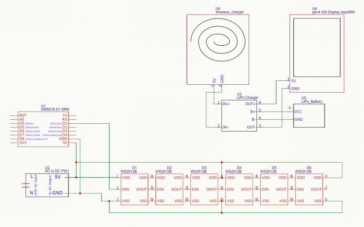
It's quite simple. The data line of the RGB strip is connected to GPIO pin 5 but can be changed in the configuration.
For the lamp to be able to connect to your WiFi and MQTT server you need to set the credentials in the first section of the code:
- #include <ESP8266WiFi.h>
- #define MAXSUBSCRIPTIONS 3
- #define SUBSCRIPTIONDATALEN 20
- #include "Adafruit_MQTT.h"
- #include "Adafruit_MQTT_Client.h"
- #include <Adafruit_NeoPixel.h>
- #include <EEPROM.h>
- /************************* SETUP *********************************/
- const char* wifiSSID = "YourWifiName";
- const char* wifiPassword = "YourWifiPassword";
- const char* mqttServer = "192.168.0.10";
- const int mqttPort = 1883; //8883 for SSL
- const char* mqttUser = "username";
- const char* mqttPassword = "password";
- const char* colorFeed = "home/sleepingRoom/lightColor";
- const char* alarmFeed = "home/sleepingRoom/lightAlarm";
- const char* time32Feed = "home/time/time32";
- const int pixelPin = 5;
- const int pixelCount = 104 + 13 + 104 + 13; //104 pixels long side, 13 pixels short side
The color and alarm time are stored in the EEPROM for reliability.
The disco modes as seen in the video are present in the code, but not yet available to be controlled remotely. It's an easy task to just add another MQTT feed which will control these.. Send me a tweet with your solution :)
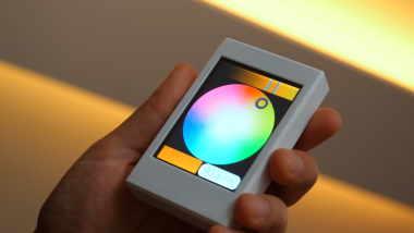
The Remote
The main driver of the remote is the 4D systems gen4-IoD-32T touch display. It provides resistive touch and has an esp8266 processor built in. The code needs also the WiFi and MQTT credentials as the Lights project so make sure you update these before upload.
The case is 3D printed. The design files can be taken from the repository. As battery I have used a decent sized LiPo with 1.3Ah but equipped with the wireless charger it probably even will work with a small 300mAh battery convenient enough as long you keep the remote placed on a charging pad.
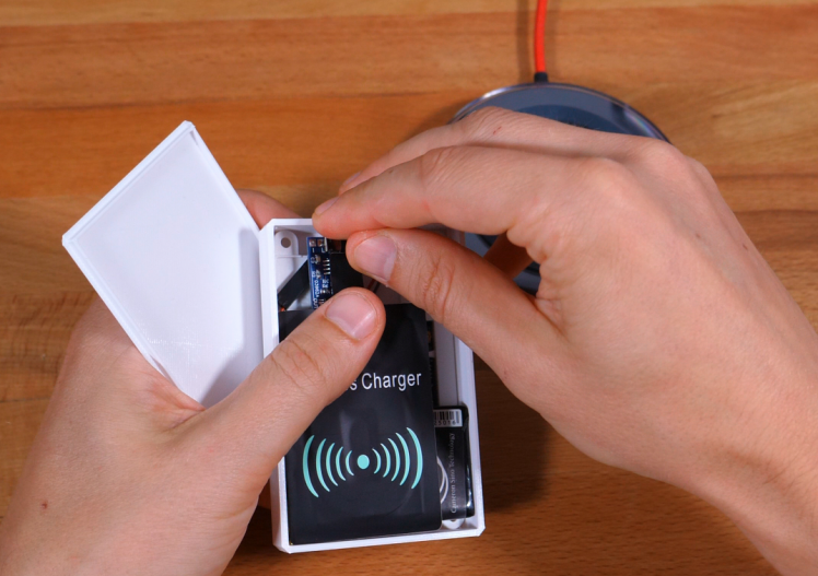
The charging pad seems to get warm even on idle. I'll try different wireless charging pads in future and update you on this.
The color and alarm time are stored in the EEPROM for convenience.
Communication
The communication is done using the MQTT protocol.
The sketches communicate on the feeds:
- "home/sleepingRoom/lightColor"
- "home/sleepingRoom/lightAlarm"
The color is sent as an BGR integer (8 bits for each color component). The alarm time is set as minutes of the day time. -1 means alarm off.
MQTT Broker
Node.RED
Node.RED is a quite convenient graphical programming platform which makes it easy to put sever tasks together especially using MQTT. In this project, it will serve the local time respecting daylight save times and it will provide a simple web-based user interface within the local network.
The default graphical Raspberry PI system images come with Node.RED pre-installed there is still some configuration to be done which you can take from this video if you don't have it installed yet.
Local Time
Since you like to be woken always at the right time the following flow:

It is triggered every 10 seconds and sends a time stamp in the local time of the raspberry pi (localization has to be set there). The time stamp is converted to seconds, hours, day etc. and sent as an simple encoded binary number. The lamp receives this number and decodes the current time. The export of the flows can be found in the repository and imported using the Node.RED UI
- var date = new Date();
- var struct = {
- "timestamp": date.getTime(),
- "year": date.getFullYear(),
- "month": date.getMonth(),
- "date": date.getDate(),
- "day": date.getDay(),
- "hour": date.getHours(),
- "minute": date.getMinutes(),
- "second": date.getSeconds()
- }
- struct.time32 =
- ((struct.year % 100) << 26) +
- (struct.month << 22) +
- (struct.date << 17) +
- (struct.hour << 12) +
- (struct.minute << 6) +
- struct.second;
- struct.offset = date.getTimezoneOffset();
- msg.payload = struct;
- return msg;
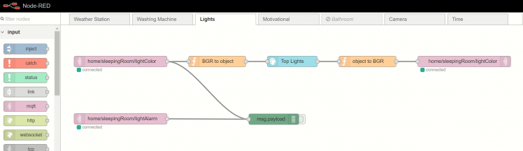
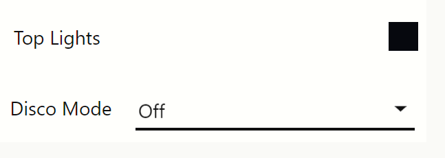
User Interface
The user interface which can also be used from mobile devices currently only provides the color setting of the lamp. It is served by Node.RED dashboard.

The flow even updates the UI if another controller is used to set the light. It's important to not let the UI color node pass the received messages, otherwise, it would trigger an endless loop.
The GBR color value which is sent over MQTT is converted to the need format of the UI node by function nodes.
[Update] Audio function and MQTT disco modes
The disco modes shown in the video can now be activated over the MQTT feed specifed also specified in the config section of the code:
- const char* discoFeed = "home/sleepingRoom/disco";
The modes are 0 to 4:0 = off1,2,3 = basic disco modes4 = audio function
A simple Node.RED dashboard flow for the disco modes can be found in the "Disco Modes flow.JSON" file from the repository

The audio function reacts to audio data received on the analog pin of the micro controller. The audio volume controls the pulse brightness. If a certain threshold is reached the color is changed.
Schematics, diagrams and documents
Code
Credits
Related products


Leave your feedback...