
Arduino + Visuino: Control Stepper Motor With Rotary Encoder

About the project
Connect Stepper Motor to Arduino and control it with Rotary Encoder - Quick and Easy!
Project info
Difficulty: Easy
Estimated time: 1 hour
License: GNU General Public License, version 3 or later (GPL3+)
Items used in this project
Hardware components

Software apps and online services
Story
Sometimes it is necessary to have a Stepper Motor follow the rotation of a Rotary Encoder for precise positioning. I have been planning Tutorial on this for a long time, but finally couple of days ago after yet another question by Visuino user, on how to do this, I decided that the time is now.
In this Tutorial, I will show you how easy it is to connect a Stepper Motor and Rotary Encoder to Arduino and program with Visuino the Stepper Motor to follow the rotations of the Rotary Encoder.
Step 1: Components
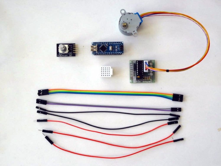
- One Arduino compatible board (I use Arduino Nano, because I have one, but any other will be just fine)
- One Rotary Encoder module I got from this cheap 37 sensors set
- One 5V Stepper Motor with Driver Board (I used 28BYJ-48 stepper with ULN2003 driver board )
- One small Breadboard (Any breadboard can be used, or any other way to connect 3 wires together)
- 8 Female-Female jumper wires
- 3 Male-Female jumper wires (Red)
1 / 5 • Picture 1

Picture 1

Picture 2

Picture 3

Picture 4

Picture 5
- If not already connected, plug the Stepper Motor connector into the Driver Board
- Connect one end of Female-Female jumper wires(Blue, Green, Yellow and Orange wires) to the IN1 to IN4 pins of the Stepper Driver(Picture 1)
- Connect Female-Female Ground(Black wire), to the Ground(-) pin the Stepper Driver Module (Picture 2)
- Connect the Female end of a Female-Male Power(Red wire), to the Power(+) pin of the Stepper Driver Module (Picture 2)
- Connect the Female End of another Female-Male Power wire(Red wire) to the 5V power pin of the Arduino board (Picture 3)
- Connect the other end of the Ground wire(Black wire) to Ground pin of the Arduino board (Picture 3)
- Connect the IN1 wire(Blue wire) to the Digital pin 2 of the Arduino board (Picture 4)
- Connect the IN2 wire(Green wire) to the Digital pin 3 of the Arduino board (Picture 4)
- Connect the IN3 wire(Yellow wire) to the Digital pin 4 of the Arduino board (Picture 4)
- Connect the IN4 wire(Orange wire) to the Digital pin 5 of the Arduino board (Picture 4)
- Picture 5 shows where are the Ground, 5V Power, and Digital 2 to Digital 5 pins of the Arduino Nano
1 / 4 • Picture 1

Picture 1

Picture 2

Picture 3

Picture 4
- Connect the Female end of a Female-Male Power(Red wire) to the power pin of the Rotary Encoder Module (Picture 1)
- Connect Ground(Black wire), Direction(Purtle wire), and Clock(Gray wire) to the Rotary Encoder Module (Picture 1)
- Connect the other end of the Power wire(Red wire) to the 5V power pin of the Arduino board(Picture 2)
- Connect the other end of the Ground wire(Black wire) to Ground pin of the Arduino board(Picture 2)
- Connect the Clock wire(Gray wire) to Digital pin 6 of the Arduino board(Picture 2)
- Connect the Direction wire(Purple wire) to Digital pin 7 of the Arduino board(Picture 2)
- Connect the Male ends of the 3 Power wires(Red wires) - from the Rotary Encoder Module, the Stepper Motor Driver, and the Arduino together as example with the help of a Breadboard (Picture 3) - In my case I used a small Breadboard
- Picture 4 shows in Red where are the Ground, Digital 6 and Digital 7 pins of the Arduino Nano. In Blue are shown the pins connected in the previous step.
1 / 2 • Picture 1

Picture 1

Picture 2
To start programming the Arduino, you will need to have the Arduino IDE installed from here: http://www.arduino.cc/.
Please be aware that there are some critical bugs in Arduino IDE 1.6.6.
Make sure that you install 1.6.7 or higher, otherwise this Tutorial will not work!
The Visuino: https://www.visuino.com also needs to be installed.
- Start Visuino as shown in the first picture
- Click on the "Tools" button on the Arduino component (Picture 1) in Visuino
- When the dialog appears, select "Arduino Nano" as shown in Picture 2
1 / 2 • Picture 1

Picture 1

Picture 2
- Type "step" in the Filter box of the Component Toolbox then select the "4 Wire Stepper Motor" component (Picture 1), and drop it in the design area
- In the Object Inspector set the value of the "Enabled" property to "False" (Picture 2)
1 / 3 • Picture 1

Picture 1

Picture 2

Picture 3
- In the Object Inspector click on the Pin button at front of the Reversed property(Picture 1), and select "Boolean SinkPin" (Picture 2)
- A new "Reversed" Pin will appear on the component (Picture 3)
1 / 3 • Picture 1

Picture 1

Picture 2

Picture 3
- Click in the "Out" box containing the pins of the Stepper component to start connecting all the Out pins at once (Picture 1)
- Move the mouse over the "Digital" input pin of the "Digital[ 2 ]" channel of the Arduino component. The Visuino will automatically spread the wires so they will connect correctly to the rest of the pins(Picture 1)
- Connect the "Out" output pin of the "Digital[ 6 ]" channel of the Arduino component to the "Reversed" input pin of the Stepper1 component (Picture 2)
- Connect the "Out" output pin of the "Digital[ 7 ]" channel of the Arduino component to the "Step" input pin of the Stepper1 component (Picture 2)
1 / 2 • Picture 1

Picture 1

Picture 2
- In Visuino, Press F9 or click on the button shown on Picture 1 to generate the Arduino code, and open the Arduino IDE
- In the Arduino IDE, click on the Upload button, to compile and upload the code (Picture 2)
1 / 2 • Picture 1

Picture 1

Picture 2
Congratulations! You have completed the project.
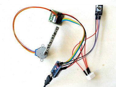
Picture 1 and the Video show the connected and powered up project.
If you rotate the Rotary Encoder, the Stepper Motor will rotate in the same direction as the encoder as you can see from the Video.
On Picture 2 you can see the complete Visuino diagram.
Also attached is the Visuino project, that I created for this Tutorial. You can download and open it in Visuino: https://www.visuino.com
Credits
Related products


Leave your feedback...