
Arduino Tft Interfacing

Made by the lonely programmer / Displays / Home Automation / Lights / Photos & Video / IoT
About the project
By using this color TFT LCD shield we can show characters, strings, button interfacing, bitmap images, etc on the color TFT LCD
Project info
Difficulty: Moderate
Estimated time: 1 hour
License: GNU General Public License, version 3 or later (GPL3+)
Items used in this project


Story
Intro: Arduino TFT Interfacing
TFT touchscreens are the amazing graphical interface which can be used with microcontrollers such as Atmel, PIC, STM, as it has a wide color range, and good graphical ability and a good mapping of pixels.
Today, we are going to Interface 2.4 inch TFT LCD Shield with Arduino.
This shield is for Arduino UNO, but I'll teach how to use it with Arduino Mega for a very logical reason, the "Program Memory".
By using this color TFT LCD shield we can show characters, strings, button interfacing, bitmap images, etc on the color TFT LCD.
Step 1: Hardware and Software Requirements

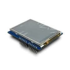
To make the shield interface with the Arduino mega, we need HARDWARE :
• Arduino mega
• TFT 2.4/2.8/3.2 inch LCD
• USB Cable
SOFTWARE :
• Arduino IDE
• UTFT Library / spfd5408 Library
The Shield is originally made for the Arduino UNO boards, which can be used with Arduino mega.
There is two main issue while using it with the Arduino UNO: "Storage memory" and pins usage.
It is difficult to use the unused pins which are available on UNO, whereas it is better with Arduino MEGA since we have more I/O pins left.
In the next step, I'll show how to edit the UTFT library to use the TFT shield
Step 2: Tweaking UTFT Lib
This library is the continuation of my ITDB02_Graph, ITDB02_Graph16 and RGB_GLCD libraries for Arduino and chipKit. As the number of supported display modules and controllers started to increase I felt it was time to make a single, universal library as it will be much easier to maintain in the future.
Arduino MEGA has 256kb of program memory. In addition, there are 54 pins.
Most of them are free to use, and the analog just 5 are taken from 16.
This library supports a number of 8bit, 16bit, and serial graphics displays, and will work with both Arduino, chipKit boards and select TI LaunchPads.
NOTE:Due to the size of the library I do not recommend using it on ATmega328 (Arduino Uno) and ATmega32U4 (Arduino Leonardo) as they only have 32KB of flash memory. It will work, but you will be severely limited in available flash memory for your application.
Steps:
- Download the UTFT Library
- Unzip the Library
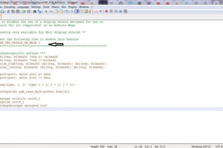
- Open UTFThardwareavr in case of Arduino or depending on the microcontroller used
- Open HW_AVR_defines using Notepad
- Uncomment Line 7 to enable UNO shield for MEGA
- Save the file and Add this Library to Arduino IDE
Now we are done with this step! In the next step, I'll show to use the library and define the pins for Arduino Mega.
Step 3: Initializing the TFT Shield
- After editing the library, Add it to the Arduino directory.
Next, I'm gonna show you how to define the right TFT module that you have
we should find its module name in the library.
- open the library file
- go to the documentation
You can see these files in the Documentation
• UTFT:
This file shows all the functions and commands that included in this library.
• UTFT_Requirement
This file has the information about the modules and how it's related to the library, like pins configurations
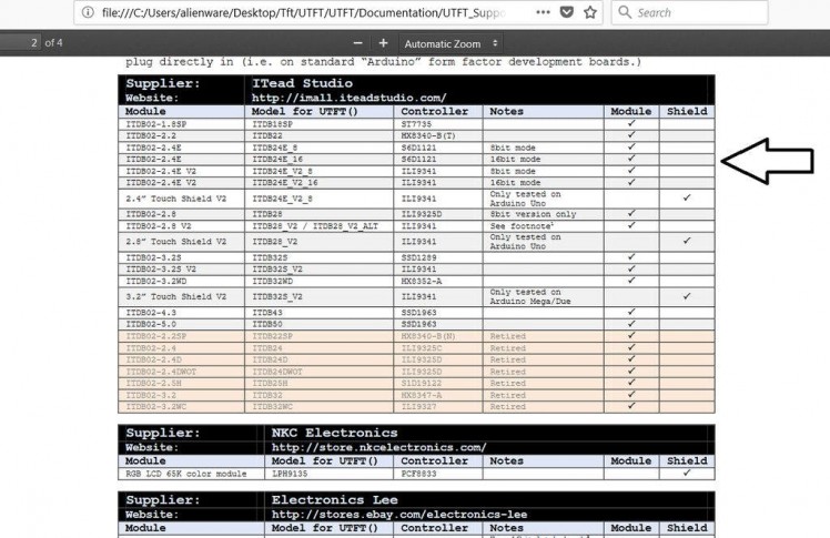
•UTFT_Supported_display_modules_&_controller
This is our target, this file has the names of the modules and shields that are supported by this library, you can see in it a list of module names and module names for the UTFT which you should use to define your module.
Steps to Define the TFT:
Open UTFT_Supported_display_modules_&_controller file from the library
- Open UTFT_Supported_display_modules_&_controller file from the library
- Find the Models for UTFT for the Modules (shield) which you have.
- Now to define a UTFT function on the Arduino IDE, we use the command :
UTFT name(module, Rs, Wr, Cs, Rst);
Open UTFT_Requirement file from the library
From the document, we know that the pins are located on the A5, A4, A3, and A2 pins.
we use the command:
UTFT myGLCD(ITDB28, 19, 18, 17, 16); # note that pins 19, 18, 17, 16 in the Arduino Mega
UTFT myGLCD(ITDB28, A5, A4, A3, A2); # note that pins A5, A4, A3, A2 in the Arduino UNO
And done! Now you can use the library examples on the Arduino IDE with the Following changes.
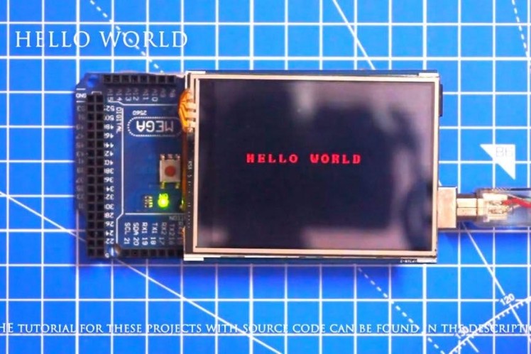
Step 4: Basic Hello World
#include <UTFT.h>
// Declare which fonts we will be using
extern uint8_t BigFont[];
extern uint8_t SevenSegNumFont[];
// Remember to change the model parameter to suit your display module!
UTFT myGLCD(ITDB28, A5, A4, A3, A2);
void setup()
{
myGLCD.InitLCD();
myGLCD.clrScr();
myGLCD.setFont(BigFont);
}
void loop()
{
myGLCD.setColor(0, 255, 0); //green
myGLCD.print("HELLO WORLD", 45, 100);
while (true) {};
}
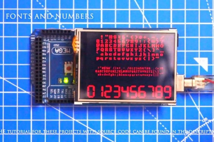
Step 5: UTFT Fonts
#include <UTFT.h>
// Declare which fonts we will be using
extern uint8_t SmallFont[];
extern uint8_t BigFont[];
extern uint8_t SevenSegNumFont[];
// Set the pins to the correct ones for your development shield
// ------------------------------------------------------------
// Arduino Uno / 2009:
// -------------------
// Standard Arduino Uno/2009 shield            : <display model>,A5,A4,A3,A2
// DisplayModule Arduino Uno TFT shield        : <display model>,A5,A4,A3,A2
//
// Arduino Mega:
// -------------------
// Standard Arduino Mega/Due shield            : <display model>,38,39,40,41
// CTE TFT LCD/SD Shield for Arduino Mega      : <display model>,38,39,40,41
//
// Remember to change the model parameter to suit your display module!
UTFT myGLCD(ITDB32S,38,39,40,41);
void setup()
{
 myGLCD.InitLCD();
 myGLCD.clrScr();
}
void loop()
{
 myGLCD.setColor(0, 255, 0);
 myGLCD.setBackColor(0, 0, 0);
 myGLCD.setFont(BigFont);
 myGLCD.print(" !"#$%&'()*+,-./", CENTER, 0);
 myGLCD.print("0123456789:;<=>?", CENTER, 16);
 myGLCD.print("@ABCDEFGHIJKLMNO", CENTER, 32);
 myGLCD.print("PQRSTUVWXYZ[\]^_", CENTER, 48);
 myGLCD.print("`abcdefghijklmno", CENTER, 64);
 myGLCD.print("pqrstuvwxyz{|}~ ", CENTER, 80);
 myGLCD.setFont(SmallFont);
 myGLCD.print(" !"#$%&'()*+,-./0123456789:;<=>?", CENTER, 120);
 myGLCD.print("@ABCDEFGHIJKLMNOPQRSTUVWXYZ[\]^_", CENTER, 132);
 myGLCD.print("`abcdefghijklmnopqrstuvwxyz{|}~ ", CENTER, 144);
 myGLCD.setFont(SevenSegNumFont);
 myGLCD.print("0123456789", CENTER, 190);
 while(1) {};
}
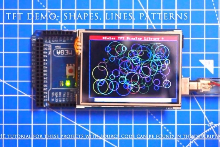
Step 6: UTFT Shapes, Lines and Pattern
#include <UTFT.h>
// Declare which fonts we will be using
extern uint8_t SmallFont[];
// Set the pins to the correct ones for your development shield
// ------------------------------------------------------------
// Arduino Uno / 2009:
// -------------------
// Standard Arduino Uno/2009 shield            : <display model>,A5,A4,A3,A2
// DisplayModule Arduino Uno TFT shield        : <display model>,A5,A4,A3,A2
//
// Arduino Mega:
// -------------------
// Standard Arduino Mega/Due shield            : <display model>,38,39,40,41
// CTE TFT LCD/SD Shield for Arduino Mega      : <display model>,38,39,40,41
//
// Remember to change the model parameter to suit your display module!
UTFT myGLCD(ITDB32S,38,39,40,41);
void setup()
{
 randomSeed(analogRead(0));
// Setup the LCD
 myGLCD.InitLCD();
 myGLCD.setFont(SmallFont);
}
void loop()
{
 int buf[318];
 int x, x2;
 int y, y2;
 int r;
// Clear the screen and draw the frame
 myGLCD.clrScr();
 myGLCD.setColor(255, 0, 0);
 myGLCD.fillRect(0, 0, 319, 13);
 myGLCD.setColor(64, 64, 64);
 myGLCD.fillRect(0, 226, 319, 239);
 myGLCD.setColor(255, 255, 255);
 myGLCD.setBackColor(255, 0, 0);
 myGLCD.print("* Universal Color TFT Display Library *", CENTER, 1);
 myGLCD.setBackColor(64, 64, 64);
 myGLCD.setColor(255,255,0);
 myGLCD.print("<http://www.RinkyDinkElectronics.com/>", CENTER, 227);
 myGLCD.setColor(0, 0, 255);
 myGLCD.drawRect(0, 14, 319, 225);
// Draw crosshairs
 myGLCD.setColor(0, 0, 255);
 myGLCD.setBackColor(0, 0, 0);
 myGLCD.drawLine(159, 15, 159, 224);
 myGLCD.drawLine(1, 119, 318, 119);
 for (int i=9; i<310; i+=10)
   myGLCD.drawLine(i, 117, i, 121);
 for (int i=19; i<220; i+=10)
   myGLCD.drawLine(157, i, 161, i);
// Draw sin-, cos- and tan-lines
 myGLCD.setColor(0,255,255);
 myGLCD.print("Sin", 5, 15);
 for (int i=1; i<318; i++)
 {
   myGLCD.drawPixel(i,119+(sin(((i*1.13)*3.14)/180)*95));
 }
 myGLCD.setColor(255,0,0);
 myGLCD.print("Cos", 5, 27);
 for (int i=1; i<318; i++)
 {
   myGLCD.drawPixel(i,119+(cos(((i*1.13)*3.14)/180)*95));
 }
 myGLCD.setColor(255,255,0);
 myGLCD.print("Tan", 5, 39);
 for (int i=1; i<318; i++)
 {
   myGLCD.drawPixel(i,119+(tan(((i*1.13)*3.14)/180)));
 }
 delay(2000);
 myGLCD.setColor(0,0,0);
 myGLCD.fillRect(1,15,318,224);
 myGLCD.setColor(0, 0, 255);
 myGLCD.setBackColor(0, 0, 0);
 myGLCD.drawLine(159, 15, 159, 224);
 myGLCD.drawLine(1, 119, 318, 119);
// Draw a moving sinewave
 x=1;
 for (int i=1; i<(318*20); i++)
 {
   x++;
   if (x==319)
     x=1;
   if (i>319)
   {
     if ((x==159)||(buf[x-1]==119))
       myGLCD.setColor(0,0,255);
     else
       myGLCD.setColor(0,0,0);
     myGLCD.drawPixel(x,buf[x-1]);
   }
   myGLCD.setColor(0,255,255);
   y=119+(sin(((i*1.1)*3.14)/180)*(90-(i / 100)));
   myGLCD.drawPixel(x,y);
   buf[x-1]=y;
 }
 delay(2000);
 myGLCD.setColor(0,0,0);
 myGLCD.fillRect(1,15,318,224);
// Draw some filled rectangles
 for (int i=1; i<6; i++)
 {
   switch (i)
   {
     case 1:
       myGLCD.setColor(255,0,255);
       break;
     case 2:
       myGLCD.setColor(255,0,0);
       break;
     case 3:
       myGLCD.setColor(0,255,0);
       break;
     case 4:
       myGLCD.setColor(0,0,255);
       break;
     case 5:
       myGLCD.setColor(255,255,0);
       break;
   }
   myGLCD.fillRect(70+(i*20), 30+(i*20), 130+(i*20), 90+(i*20));
 }
 delay(2000);
 myGLCD.setColor(0,0,0);
 myGLCD.fillRect(1,15,318,224);
// Draw some filled, rounded rectangles
 for (int i=1; i<6; i++)
 {
   switch (i)
   {
     case 1:
       myGLCD.setColor(255,0,255);
       break;
     case 2:
       myGLCD.setColor(255,0,0);
       break;
     case 3:
       myGLCD.setColor(0,255,0);
       break;
     case 4:
       myGLCD.setColor(0,0,255);
       break;
     case 5:
       myGLCD.setColor(255,255,0);
       break;
   }
   myGLCD.fillRoundRect(190-(i*20), 30+(i*20), 250-(i*20), 90+(i*20));
 }
 delay(2000);
 myGLCD.setColor(0,0,0);
 myGLCD.fillRect(1,15,318,224);
// Draw some filled circles
 for (int i=1; i<6; i++)
 {
   switch (i)
   {
     case 1:
       myGLCD.setColor(255,0,255);
       break;
     case 2:
       myGLCD.setColor(255,0,0);
       break;
     case 3:
       myGLCD.setColor(0,255,0);
       break;
     case 4:
       myGLCD.setColor(0,0,255);
       break;
     case 5:
       myGLCD.setColor(255,255,0);
       break;
   }
   myGLCD.fillCircle(100+(i*20),60+(i*20), 30);
 }
 delay(2000);
 myGLCD.setColor(0,0,0);
 myGLCD.fillRect(1,15,318,224);
// Draw some lines in a pattern
 myGLCD.setColor (255,0,0);
 for (int i=15; i<224; i+=5)
 {
   myGLCD.drawLine(1, i, (i*1.44)-10, 224);
 }
 myGLCD.setColor (255,0,0);
 for (int i=224; i>15; i-=5)
 {
   myGLCD.drawLine(318, i, (i*1.44)-11, 15);
 }
 myGLCD.setColor (0,255,255);
 for (int i=224; i>15; i-=5)
 {
   myGLCD.drawLine(1, i, 331-(i*1.44), 15);
 }
 myGLCD.setColor (0,255,255);
 for (int i=15; i<224; i+=5)
 {
   myGLCD.drawLine(318, i, 330-(i*1.44), 224);
 }
 delay(2000);
 myGLCD.setColor(0,0,0);
 myGLCD.fillRect(1,15,318,224);
// Draw some random circles
 for (int i=0; i<100; i++)
 {
   myGLCD.setColor(random(255), random(255), random(255));
   x=32+random(256);
   y=45+random(146);
   r=random(30);
   myGLCD.drawCircle(x, y, r);
 }
 delay(2000);
 myGLCD.setColor(0,0,0);
 myGLCD.fillRect(1,15,318,224);
// Draw some random rectangles
 for (int i=0; i<100; i++)
 {
   myGLCD.setColor(random(255), random(255), random(255));
   x=2+random(316);
   y=16+random(207);
   x2=2+random(316);
   y2=16+random(207);
   myGLCD.drawRect(x, y, x2, y2);
 }
 delay(2000);
 myGLCD.setColor(0,0,0);
 myGLCD.fillRect(1,15,318,224);
// Draw some random rounded rectangles
 for (int i=0; i<100; i++)
 {
   myGLCD.setColor(random(255), random(255), random(255));
   x=2+random(316);
   y=16+random(207);
   x2=2+random(316);
   y2=16+random(207);
   myGLCD.drawRoundRect(x, y, x2, y2);
 }
 delay(2000);
 myGLCD.setColor(0,0,0);
 myGLCD.fillRect(1,15,318,224);
 for (int i=0; i<100; i++)
 {
   myGLCD.setColor(random(255), random(255), random(255));
   x=2+random(316);
   y=16+random(209);
   x2=2+random(316);
   y2=16+random(209);
   myGLCD.drawLine(x, y, x2, y2);
 }
 delay(2000);
 myGLCD.setColor(0,0,0);
 myGLCD.fillRect(1,15,318,224);
 for (int i=0; i<10000; i++)
 {
   myGLCD.setColor(random(255), random(255), random(255));
   myGLCD.drawPixel(2+random(316), 16+random(209));
 }
 delay(2000);
 myGLCD.fillScr(0, 0, 255);
 myGLCD.setColor(255, 0, 0);
 myGLCD.fillRoundRect(80, 70, 239, 169);
 myGLCD.setColor(255, 255, 255);
 myGLCD.setBackColor(255, 0, 0);
 myGLCD.print("That's it!", CENTER, 93);
 myGLCD.print("Restarting in a", CENTER, 119);
 myGLCD.print("few seconds...", CENTER, 132);
 myGLCD.setColor(0, 255, 0);
 myGLCD.setBackColor(0, 0, 255);
 myGLCD.print("Runtime: (msecs)", CENTER, 210);
 myGLCD.printNumI(millis(), CENTER, 225);
 delay (10000);
}
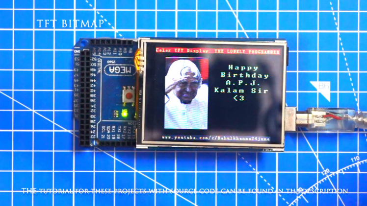
Step 7: UTFT Bitmap
#include <UTFT.h>
#include <avr/pgmspace.h>
// Declare which fonts we will be using
extern uint8_t SmallFont[];
// Set the pins to the correct ones for your development shield
// ------------------------------------------------------------
// Arduino Uno / 2009:
// -------------------
// Standard Arduino Uno/2009 shield            : <display model>,A5,A4,A3,A2
// DisplayModule Arduino Uno TFT shield        : <display model>,A5,A4,A3,A2
//
// Arduino Mega:
// -------------------
// Standard Arduino Mega/Due shield            : <display model>,38,39,40,41
// CTE TFT LCD/SD Shield for Arduino Mega      : <display model>,38,39,40,41
//
// Remember to change the model parameter to suit your display module!
UTFT myGLCD(ITDB32S,A5,A4,A3,A2);
extern unsigned int info[0x400];
extern unsigned int icon[0x400];
extern unsigned int tux[0x400];
void setup()
{
 myGLCD.InitLCD();
 myGLCD.setFont(SmallFont);
}
void loop()
{
 myGLCD.fillScr(255, 255, 255);
 myGLCD.setColor(255, 255, 255);
 myGLCD.print(" *** A 10 by 7 grid of a 32x32 icon *** ", CENTER, 228);
 for (int x=0; x<10; x++)
   for (int y=0; y<7; y++)
     myGLCD.drawBitmap (x*32, y*32, 32, 32, info);
 delay(5000);
 myGLCD.fillScr(255, 255, 255);
 myGLCD.setColor(255, 255, 255);
 myGLCD.print("   Two different icons in scale 1 to 4  ", CENTER, 228);
 int x=0;
 for (int s=0; s<4; s++)
 {
   x+=(s*32);
   myGLCD.drawBitmap (x, 0, 32, 32, tux, s+1);
 }
 x=0;
 for (int s=4; s>0; s--)
 {
   myGLCD.drawBitmap (x, 224-(s*32), 32, 32, icon, s);
   x+=(s*32);
 }
 delay(5000);
}
Step 8: Button Interfacing

#include <UTFT.h>
#include <URTouch.h>
// Initialize display
// ------------------
// Set the pins to the correct ones for your development board
// -----------------------------------------------------------
// Standard Arduino Uno/2009 Shield : <display model>,19,18,17,16
// Standard Arduino Mega/Due shield : <display model>,38,39,40,41
// CTE TFT LCD/SD Shield for Arduino Due : <display model>,25,26,27,28
// Teensy 3.x TFT Test Board : <display model>,23,22, 3, 4
// ElecHouse TFT LCD/SD Shield for Arduino Due : <display model>,22,23,31,33
//
// Remember to change the model parameter to suit your display module!
UTFT myGLCD(ITDB32S,38,39,40,41);
// Initialize touchscreen
// ----------------------
// Set the pins to the correct ones for your development board
// -----------------------------------------------------------
// Standard Arduino Uno/2009 Shield : 15,10,14, 9, 8
// Standard Arduino Mega/Due shield : 6, 5, 4, 3, 2
// CTE TFT LCD/SD Shield for Arduino Due : 6, 5, 4, 3, 2
// Teensy 3.x TFT Test Board : 26,31,27,28,29
// ElecHouse TFT LCD/SD Shield for Arduino Due : 25,26,27,29,30
//
URTouch myTouch( 6, 5, 4, 3, 2);
// Declare which fonts we will be using
extern uint8_t BigFont[];
int x, y;
char stCurrent[20]="";
int stCurrentLen=0;
char stLast[20]="";
/*************************
** Custom functions **
*************************/
void drawButtons()
{
// Draw the upper row of buttons
for (x=0; x<5; x++)
{
myGLCD.setColor(0, 0, 255);
myGLCD.fillRoundRect (10+(x*60), 10, 60+(x*60), 60);
myGLCD.setColor(255, 255, 255);
myGLCD.drawRoundRect (10+(x*60), 10, 60+(x*60), 60);
myGLCD.printNumI(x+1, 27+(x*60), 27);
}
// Draw the center row of buttons
for (x=0; x<5; x++)
{
myGLCD.setColor(0, 0, 255);
myGLCD.fillRoundRect (10+(x*60), 70, 60+(x*60), 120);
myGLCD.setColor(255, 255, 255);
myGLCD.drawRoundRect (10+(x*60), 70, 60+(x*60), 120);
if (x<4)
myGLCD.printNumI(x+6, 27+(x*60), 87);
}
myGLCD.print("0", 267, 87);
// Draw the lower row of buttons
myGLCD.setColor(0, 0, 255);
myGLCD.fillRoundRect (10, 130, 150, 180);
myGLCD.setColor(255, 255, 255);
myGLCD.drawRoundRect (10, 130, 150, 180);
myGLCD.print("Clear", 40, 147);
myGLCD.setColor(0, 0, 255);
myGLCD.fillRoundRect (160, 130, 300, 180);
myGLCD.setColor(255, 255, 255);
myGLCD.drawRoundRect (160, 130, 300, 180);
myGLCD.print("Enter", 190, 147);
myGLCD.setBackColor (0, 0, 0);
}
void updateStr(int val)
{
if (stCurrentLen<20)
{
stCurrent[stCurrentLen]=val;
stCurrent[stCurrentLen+1]='�';
stCurrentLen++;
myGLCD.setColor(0, 255, 0);
myGLCD.print(stCurrent, LEFT, 224);
}
else
{
myGLCD.setColor(255, 0, 0);
myGLCD.print("BUFFER FULL!", CENTER, 192);
delay(500);
myGLCD.print(" ", CENTER, 192);
delay(500);
myGLCD.print("BUFFER FULL!", CENTER, 192);
delay(500);
myGLCD.print(" ", CENTER, 192);
myGLCD.setColor(0, 255, 0);
}
}
// Draw a red frame while a button is touched
void waitForIt(int x1, int y1, int x2, int y2)
{
myGLCD.setColor(255, 0, 0);
myGLCD.drawRoundRect (x1, y1, x2, y2);
while (myTouch.dataAvailable())
myTouch.read();
myGLCD.setColor(255, 255, 255);
myGLCD.drawRoundRect (x1, y1, x2, y2);
}
/*************************
** Required functions **
*************************/
void setup()
{
// Initial setup
myGLCD.InitLCD();
myGLCD.clrScr();
myTouch.InitTouch();
myTouch.setPrecision(PREC_MEDIUM);
myGLCD.setFont(BigFont);
myGLCD.setBackColor(0, 0, 255);
drawButtons();
}
void loop()
{
while (true)
{
if (myTouch.dataAvailable())
{
myTouch.read();
x=myTouch.getX();
y=myTouch.getY();
if ((y>=10) && (y<=60)) // Upper row
{
if ((x>=10) && (x<=60)) // Button: 1
{
waitForIt(10, 10, 60, 60);
updateStr('1');
}
if ((x>=70) && (x<=120)) // Button: 2
{
waitForIt(70, 10, 120, 60);
updateStr('2');
}
if ((x>=130) && (x<=180)) // Button: 3
{
waitForIt(130, 10, 180, 60);
updateStr('3');
}
if ((x>=190) && (x<=240)) // Button: 4
{
waitForIt(190, 10, 240, 60);
updateStr('4');
}
if ((x>=250) && (x<=300)) // Button: 5
{
waitForIt(250, 10, 300, 60);
updateStr('5');
}
}
if ((y>=70) && (y<=120)) // Center row
{
if ((x>=10) && (x<=60)) // Button: 6
{
waitForIt(10, 70, 60, 120);
updateStr('6');
}
if ((x>=70) && (x<=120)) // Button: 7
{
waitForIt(70, 70, 120, 120);
updateStr('7');
}
if ((x>=130) && (x<=180)) // Button: 8
{
waitForIt(130, 70, 180, 120);
updateStr('8');
}
if ((x>=190) && (x<=240)) // Button: 9
{
waitForIt(190, 70, 240, 120);
updateStr('9');
}
if ((x>=250) && (x<=300)) // Button: 0
{
waitForIt(250, 70, 300, 120);
updateStr('0');
}
}
if ((y>=130) && (y<=180)) // Upper row
{
if ((x>=10) && (x<=150)) // Button: Clear
{
waitForIt(10, 130, 150, 180);
stCurrent[0]='�';
stCurrentLen=0;
myGLCD.setColor(0, 0, 0);
myGLCD.fillRect(0, 224, 319, 239);
}
if ((x>=160) && (x<=300)) // Button: Enter
{
waitForIt(160, 130, 300, 180);
if (stCurrentLen>0)
{
for (x=0; x<stCurrentLen+1; x++)
{
stLast[x]=stCurrent[x];
}
stCurrent[0]='�';
stCurrentLen=0;
myGLCD.setColor(0, 0, 0);
myGLCD.fillRect(0, 208, 319, 239);
myGLCD.setColor(0, 255, 0);
myGLCD.print(stLast, LEFT, 208);
}
else
{
myGLCD.setColor(255, 0, 0);
myGLCD.print("BUFFER EMPTY", CENTER, 192);
delay(500);
myGLCD.print(" ", CENTER, 192);
delay(500);
myGLCD.print("BUFFER EMPTY", CENTER, 192);
delay(500);
myGLCD.print(" ", CENTER, 192);
myGLCD.setColor(0, 255, 0);
}
}
}
}
}
}
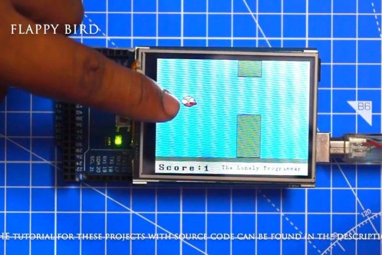
Step 9: Flappy Bird
#include <UTFT.h>
#include <UTouch.h>
#include <EEPROM.h>
//==== Creating Objects
UTFT    myGLCD(SSD1289,38,39,40,41); //Parameters should be adjusted to your Display/Schield model
UTouch  myTouch( 6, 5, 4, 3, 2);
//==== Defining Fonts
extern uint8_t SmallFont[];
extern uint8_t BigFont[];
extern uint8_t SevenSegNumFont[];
extern unsigned int bird01[0x41A]; // Bird Bitmap
int x, y; // Variables for the coordinates where the display has been pressed
// Floppy Bird
int xP = 319;
int yP = 100;
int yB = 50;
int movingRate = 3;
int fallRateInt = 0;
float fallRate = 0;
int score = 0;
int lastSpeedUpScore = 0;
int highestScore;
boolean screenPressed = false;
boolean gameStarted = false;
void setup() {
 // Initiate display
 myGLCD.InitLCD();
 myGLCD.clrScr();
 myTouch.InitTouch();
 myTouch.setPrecision(PREC_MEDIUM);
 highestScore = EEPROM.read(0); // Read the highest score from the EEPROM
 initiateGame(); // Initiate the game
}
void loop() {
   xP=xP-movingRate; // xP - x coordinate of the pilars; range: 319 - (-51)
   drawPilars(xP, yP); // Draws the pillars
   // yB - y coordinate of the bird which depends on value of the fallingRate variable
   yB+=fallRateInt;
   fallRate=fallRate+0.4; // Each inetration the fall rate increase so that we can the effect of acceleration/ gravity
   fallRateInt= int(fallRate);
   // Checks for collision
   if(yB>=180 || yB<=0){ // top and bottom
     gameOver();
   }
   if((xP<=85) && (xP>=5) && (yB<=yP-2)){ // upper pillar
     gameOver();
   }
   if((xP<=85) && (xP>=5) && (yB>=yP+60)){ // lower pillar
     gameOver();
   }
   // Draws the bird
   drawBird(yB);
   // After the pillar has passed through the screen
   if (xP<=-51){
     xP=319; // Resets xP to 319
     yP = rand() % 100+20; // Random number for the pillars height
     score++; // Increase score by one
   }
   //==== Controlling the bird
   if (myTouch.dataAvailable()&& !screenPressed) {
      fallRate=-6; // Setting the fallRate negative will make the bird jump
      screenPressed = true;
   }
   // Doesn't allow holding the screen / you must tap it
   else if ( !myTouch.dataAvailable() && screenPressed){
     screenPressed = false;
   }
   // After each five points, increases the moving rate of the pillars
   if ((score - lastSpeedUpScore) == 5) {
     lastSpeedUpScore = score;
     movingRate++;
   }
}
// ===== initiateGame - Custom Function
void initiateGame() {
 myGLCD.clrScr();
 // Blue background
 myGLCD.setColor(114, 198, 206);
 myGLCD.fillRect(0,0,319,239);
 // Ground
 myGLCD.setColor(221,216,148);
 myGLCD.fillRect(0, 215, 319, 239);
 myGLCD.setColor(47,175,68);
 myGLCD.fillRect(0, 205, 319, 214);
 // Text
 myGLCD.setColor(0, 0, 0);
 myGLCD.setBackColor(221, 216, 148);
 myGLCD.setFont(BigFont);
 myGLCD.print("Score:",5,220);
 myGLCD.setFont(SmallFont);
 myGLCD.print("HowToMechatronics.com", 140, 220);
 myGLCD.setColor(0, 0, 0);
 myGLCD.setBackColor(114, 198, 206);
 myGLCD.print("Highest Score: ",5,5);
 myGLCD.printNumI(highestScore, 120, 6);
 myGLCD.print(">RESET<",255,5);
 myGLCD.drawLine(0,23,319,23);
 myGLCD.print("TAP TO START",CENTER,100);
 drawBird(yB); // Draws the bird
 // Wait until we tap the sreen
 while (!gameStarted) {
   if (myTouch.dataAvailable()) {
   myTouch.read();
   x=myTouch.getX();
   y=myTouch.getY();
   // Reset higest score
   if ((x>=250) && (x<=319) &&(y>=0) && (y<=28)) {
   highestScore = 0;
   myGLCD.setColor(114, 198, 206);
   myGLCD.fillRect(120, 0, 150, 22);
   myGLCD.setColor(0, 0, 0);
   myGLCD.printNumI(highestScore, 120, 5);
   }
   if ((x>=0) && (x<=319) &&(y>=30) && (y<=239)) {
   gameStarted = true;
   myGLCD.setColor(114, 198, 206);
   myGLCD.fillRect(0, 0, 319, 32);
   }
 }
 }
 // Clears the text "TAP TO START" before the game start
 myGLCD.setColor(114, 198, 206);
 myGLCD.fillRect(85, 100, 235, 116);
}
// ===== drawPlillars - Custom Function
void drawPilars(int x, int y) {
   if (x>=270){
     myGLCD.setColor(0, 200, 20);
     myGLCD.fillRect(318, 0, x, y-1);
     myGLCD.setColor(0, 0, 0);
     myGLCD.drawRect(319, 0, x-1, y);
     myGLCD.setColor(0, 200, 20);
     myGLCD.fillRect(318, y+81, x, 203);
     myGLCD.setColor(0, 0, 0);
     myGLCD.drawRect(319, y+80, x-1, 204);
   }
   else if( x<=268) {
     // Draws blue rectangle right of the pillar
     myGLCD.setColor(114, 198, 206);
     myGLCD.fillRect(x+51, 0, x+60, y);
     // Draws the pillar
     myGLCD.setColor(0, 200, 20);
     myGLCD.fillRect(x+49, 1, x+1, y-1);
     // Draws the black frame of the pillar
     myGLCD.setColor(0, 0, 0);
     myGLCD.drawRect(x+50, 0, x, y);
     // Draws the blue rectangle left of the pillar
     myGLCD.setColor(114, 198, 206);
     myGLCD.fillRect(x-1, 0, x-3, y);
     // The bottom pillar
     myGLCD.setColor(114, 198, 206);
     myGLCD.fillRect(x+51, y+80, x+60, 204);
     myGLCD.setColor(0, 200, 20);
     myGLCD.fillRect(x+49, y+81, x+1, 203);
     myGLCD.setColor(0, 0, 0);
     myGLCD.drawRect(x+50, y+80, x, 204);
     myGLCD.setColor(114, 198, 206);
     myGLCD.fillRect(x-1, y+80, x-3, 204);
 }
 // Draws the score
 myGLCD.setColor(0, 0, 0);
 myGLCD.setBackColor(221, 216, 148);
 myGLCD.setFont(BigFont);
 myGLCD.printNumI(score, 100, 220);
}
//====== drawBird() - Custom Function
void drawBird(int y) {
 // Draws the bird - bitmap
 myGLCD.drawBitmap (50, y, 35, 30, bird01);
 // Draws blue rectangles above and below the bird in order to clear its previus state
 myGLCD.setColor(114, 198, 206);
 myGLCD.fillRoundRect(50,y,85,y-6);
 myGLCD.fillRoundRect(50,y+30,85,y+36);
}
//======== gameOver() - Custom Function
void gameOver() {
 delay(3000); // 1 second
 // Clears the screen and prints the text
 myGLCD.clrScr();
 myGLCD.setColor(255, 255, 255);
 myGLCD.setBackColor(0, 0, 0);
 myGLCD.setFont(BigFont);
 myGLCD.print("GAME OVER", CENTER, 40);
 myGLCD.print("Score:", 100, 80);
 myGLCD.printNumI(score,200, 80);
 myGLCD.print("Restarting...", CENTER, 120);
 myGLCD.setFont(SevenSegNumFont);
 myGLCD.printNumI(2,CENTER, 150);
 delay(1000);
 myGLCD.printNumI(1,CENTER, 150);
 delay(1000);
 // Writes the highest score in the EEPROM
 if (score > highestScore) {
   highestScore = score;
   EEPROM.write(0,highestScore);
 }
 // Resets the variables to start position values
 xP=319;
 yB=50;
 fallRate=0;
 score = 0;
 lastSpeedUpScore = 0;
 movingRate = 3;
 gameStarted = false;
 // Restart game
 initiateGame();
}
Step 10: Working of the Project
Give a thumbs up if it really helped you and do follow my channel for interesting projects :)
Share this video if you like.
Happy to have you subscribed: https://www.youtube.com/channel/UCks-9JSnVb22dlqtMgPjrlg/videos
Thanks for reading!
Schematics, diagrams and documents
Code
Credits
the lonely programmer
Passionate Techie ! Robotics | Electronics | Programming Hey Geek! If you are in search of electronics projects, Arduino based projects or any Micro-controller based projects, this channel is for you. In this channel, we build electronics projects using the impressive and low-cost boards that are available today. If you are a maker or if you want to learn how to make your own Arduino projects and other interesting Robots, do subscribe the channel to be a part of this community. We develop our own hardware and software projects and will try to build something new. Don’t worry if you don’t know how to program. I'll share the algorithm if you face any difficulties.
Related products


Leave your feedback...