
Arduino Steampunk Goggles - Simple Diy

Made by Ron / Art / Games & Gaming / Kids & Family / Star Wars
About the project
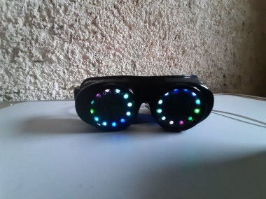
In this Tutorial we will learn how to make the Legendary SteamPunk Goggles that change colors using LED Rings and Arduino.
Project info
Difficulty: Easy
Platforms: Adafruit, Arduino, Visuino
Estimated time: 1 hour
License: GNU General Public License, version 3 or later (GPL3+)
Items used in this project
Hardware components

Story
In this Tutorial we will learn how to make the Legendary SteamPunk Goggles that change colors using LED Rings and Arduino.
Watch the video!
Step 1: What You Will Need
1 / 4

- Welding goggles
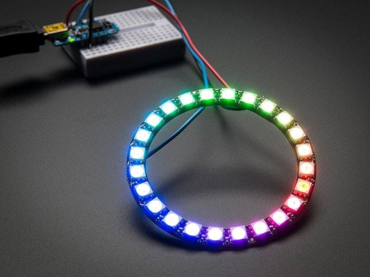
- 2X NeoPixel - Ws2812 RGB LED Ring (with 12 LEDs)
- Arduino UNO (or any other Arduino)
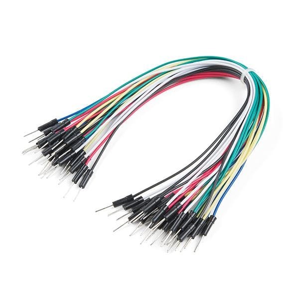
- Jumper wires
- Visuino software: Download Visuino
- Note: to use Arduino Nano (because it is smaller) just connect it to the same pins and in Visuino instead of Arduino UNO select Arduino Nano
Step 2: Circuit
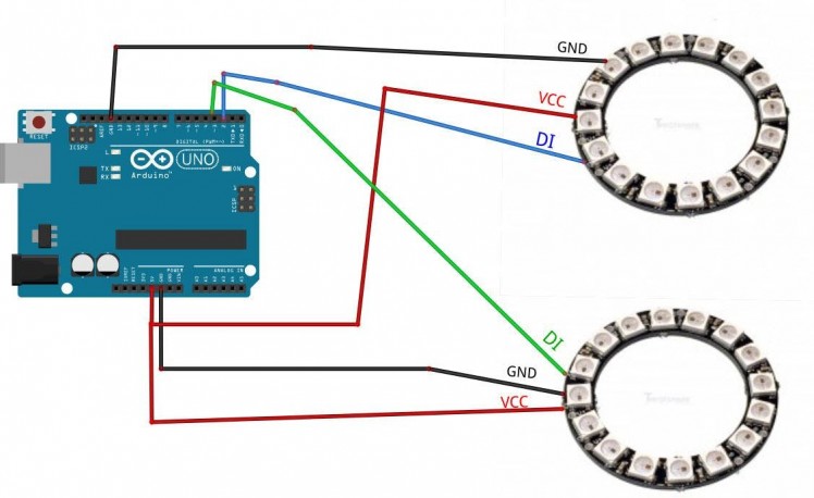
- Connect Arduino board pin 5V to the first LedRing pin VCC
- Connect Arduino board pin GND to the first LedRing pin GND
- Connect Arduino board Digital pin 2 to the first LedRing pin DI
- Connect Arduino board pin 5V to the second LedRing pin VCC
- Connect Arduino board pin GND to the second LedRing pin GND
- Connect Arduino board Digital pin 3 to the second LedRing pin DI
Wire everything according to the schematic then use a Hot glue and mount each LedRing on the goggles
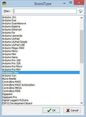
Step 3: Start Visuino, and Select the Arduino UNO Board Type
1 / 2

The Visuino: https://www.visuino.eu also needs to be installed. Download Free version or register for a Free Trial.
Start Visuino as shown in the first picture Click on the "Tools" button on the Arduino component (Picture 1) in Visuino When the dialog appears, select "Arduino UNO" as shown on Picture 2
Step 4: In Visuino Add Components
1 / 5
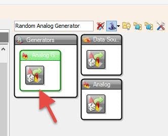
- Add 2X "Random Analog Generator" component
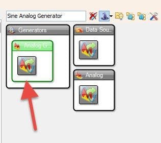
- Add "Sine Analog Generator" component
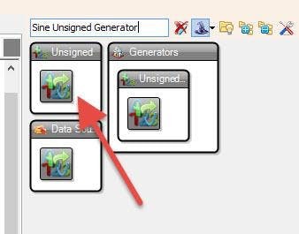
- Add "Sine Unsigned Generator" component
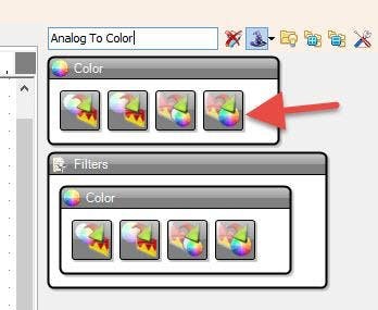
- Add "Analog To Color" component
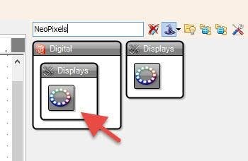
- Add 2X "NeoPixels" component
Step 5: In Visuino Set Components
1 / 3
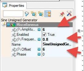
Select "SineUnsignedGenerator1" and in the properties window set Amplitude to 6, Frequency (Hz) to 0.8 and Offset to 6
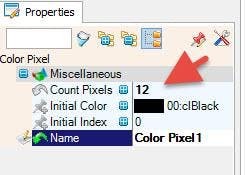
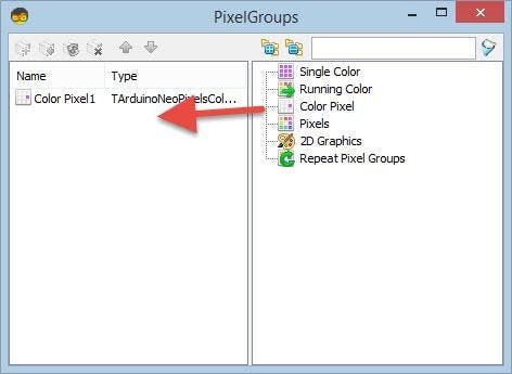
- Double click on the "NeoPixels1" and in the "PixelGroups" window drag "Color Pixel" to the left side and in the properties window set "Count Pixels" to 12 PixelGroups" window
- Double click on the "NeoPixels2" and in the "PixelGroups" window drag "Color Pixel" to the left side and in the properties window set "Count Pixels" to 12 < this is the amount of LEDs on the LEDRingClose the "PixelGroups" window
Step 6: In Visuino Connect Components
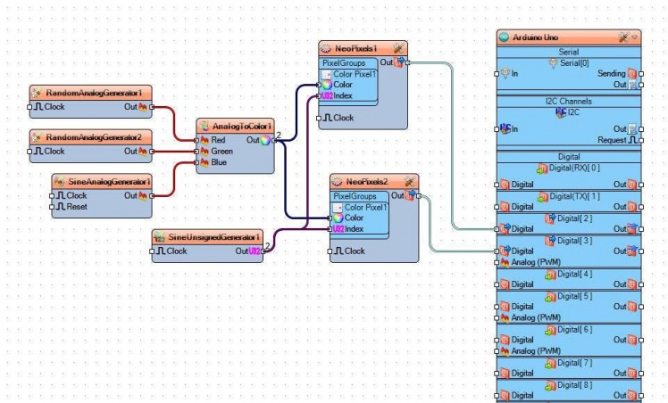
- Connect "RandomAnalogGenerator1" pin Out to "AnalogToColor1" pin Red
- Connect "RandomAnalogGenerator2" pin Out to "AnalogToColor1" pin Green
- Connect "SineAnalogGenerator1" pin Out to "AnalogToColor1" pin Blue
- Connect "AnalogToColor1" pin Out to "NeoPixels1" pin Color
- Connect "AnalogToColor1" pin Out to "NeoPixels2" pin Color
- Connect "SineUnsignedGenerator1" pin Out to "NeoPixels1" pin Index
- Connect "SineUnsignedGenerator1" pin Out to "NeoPixels2" pin Index
- Connect "NeoPixels1" pin Out to Arduino digital pin 2
- Connect "NeoPixels2" pin Out to Arduino digital pin 3
Step 7: Generate, Compile, and Upload the Arduino Code
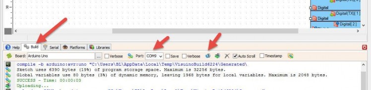
In Visuino, at the bottom click on the "Build" Tab, make sure the correct port is selected, then click on the "Compile/Build and Upload" button.
Step 8: Play
If you power the Arduino module, the LEDRings will start to change colors.
Congratulations! You have completed your project with Visuino. Also attached is the Visuino project, that I created for this tutorial, you can download it and open it in Visuino: https://www.visuino.eu
Step 9: Powering
If you plan to power the Arduino with a battery you can use a PowerBank that has the USB connector so you can connect it easily.
If you plan to use a 9V battery or similar then using wires connect a battery negative pin (-) to Arduino pin [GND] and connect a battery positive pin (+) to Arduino pin [VIN]
Schematics, diagrams and documents
Code
Credits
Related products


Leave your feedback...