
Arduino Skeleton Seven-segment Clock

About the project
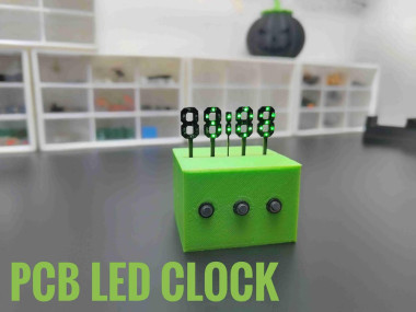
Let's build a new Style clock using Arduino and PCB
Project info
Difficulty: Moderate
Platforms: Arduino, Autodesk, TI LaunchPad, JLCPCB, Taoglas
Estimated time: 7 hours
License: Creative Commons Attribution-NoDerivs CC BY-ND version 4.0 or later (CC BY-ND 4+)
Items used in this project
Hardware components

|
Battery, 3.7 V | x 1 | |
|
|
CUSTOM PCB from JLCPCB | x 1 | |
|
|
tp 4056 | x 1 | |
|
|
3v battery | x 1 | |
|
|
1k resistor 0805 | x 1 | |
|
|
0805 led | x 1 | |
|
|
Real Time Clock (RTC) | x 1 | |
|
|
Arduino Nano R3 | x 1 |
View all
Hand tools and fabrication machines
Story
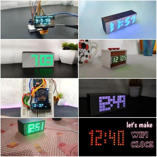
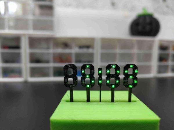
If you are a regular follower of mine, then you might have seen my clock-making tutorials. These are clocks of different types and styles that I have made. in this tutorial also I am showing how to build a clock but this one has to be a unique design. So After thinking, searching and designing, I came up with a new skeleton design, the projected structure looks similar to the skeleton that’s why I am calling skeleton clock. The main clock structure was made by carving the PCB. I think it is beautiful. now let’s see how I made this. Let’s get started!

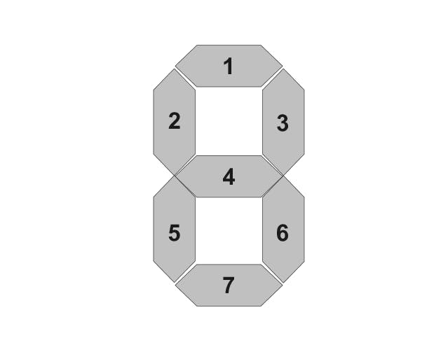
To show the time, we need displays, and the best DIY display is a 7-segment display. we can build seven-segment displays very easily and with different styles. So here I am going to use 7 LEDs to make the 7-segment display.
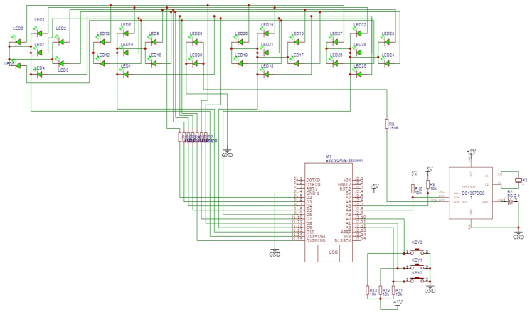
I used EasyEDA to design my circuit and PCB. Here is the circuit diagram, the circuit has a total of 30 LEDs, that is we need four seven-segment digits and two leads to show the time. Two LEDs also act as the separator between the 4 digits. Here, I am using an Arduino Nano as the brain of the circuit and also included a DS1307 RTC IC to save time. The other components are crystals and resistors. in this circuit also I added 3 push buttons for setting the time.
Components Needed for Making Skelton Clock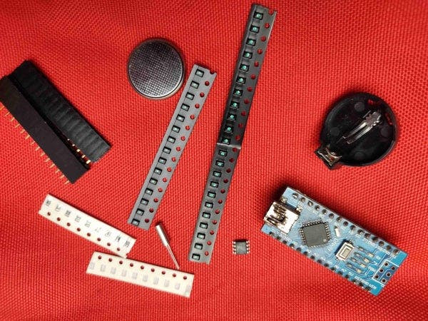
- Arduino nano - 1 nos
- DS1307 RTC ic -1 nos
- 32.768Khz crystal- 1 nos
- LEDs 0805- 30 nos
- resistors 1k 0805- 7 nos
- resistors 10k 0805- 5nos
- coin cell battery 3v - 1 nos
- coin cell battery holder- 1 nos
- push buttons - 3 nos
- on/off switch - 1 nos
- female header pins 40 pin- 1 nos
- 3.7volt battery- 1 nos
- TP4056 charger module- 1 nos
- printed PCB -1 nos
- 3D printed part

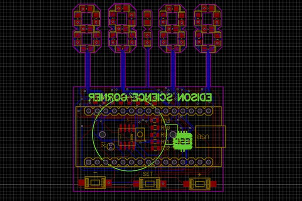
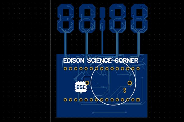
To build the skeletal structure we have to convert this circuit into a PCB. Next, I converted the circuit diagram into a PCB. I arranged the LEDs in a seven-segment shape and designed the PCB like this. Then, I generated and downloaded the Gerber file for PCB fabrication.
2D view of Skelton Clock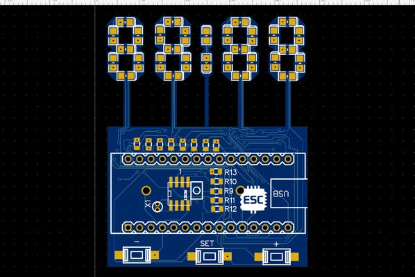
PCB Fabrication

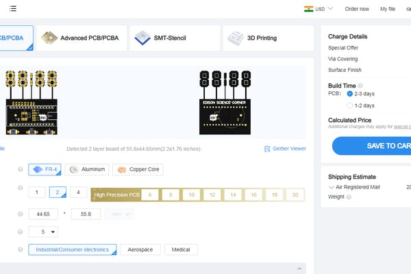
To fabricate the PCBs, I went to JLCPCB.com.JLCPCB offers only $2 for 5 PCBs and their PCB assembly starts from zero dollars. Ordering PCB in JLCPCBis very easy. To order, just click on "Order Now" and select your Gerber file. After that, you can select the colour, thickness, quantity, etc. Here, I choose the black colour. You can choose your favourite PCB colour from plenty of options. Finally, I selected the shipping method and placed the order.
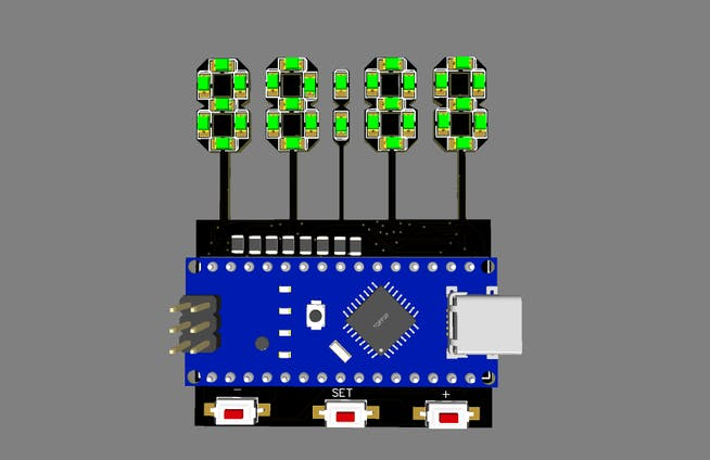
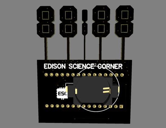
Fabricated PCBs
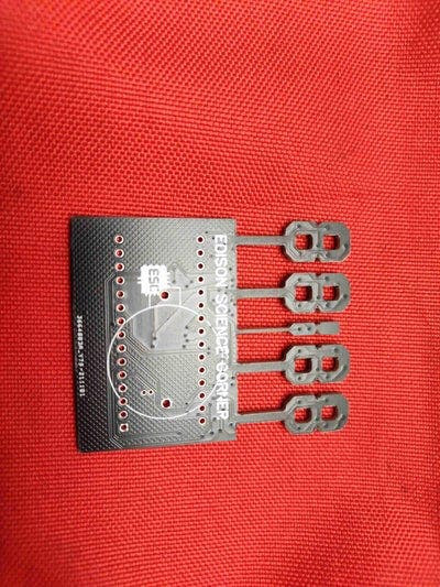

After two weeks, I received the PCBs from JLCPCB. The PCB quality was excellent, as expected. I love the quality of PCBs made by jlcpcb.com. check out jlcpcb to get high-quality PCB service at a low cost.
PCB AssemblyNow, let's solder the components to the PCB. Let's start with the SMD components. To solder SMD components, we have lots of options like hotgun method, the reflow method, the oven method and the normal soldering method etc. you will not get good finishing if you solder SMD components using a soldering iron. Hot air is a better option but components alignment may be changed by the airflow. The best way is to use a reflow oven or reflow hot plate. I am going to use the reflow method. For that, I applied the solder paste to the pads using the syringe. Next, I placed the components Using an ESD Tweezer, one by one.
Hotplate Reflow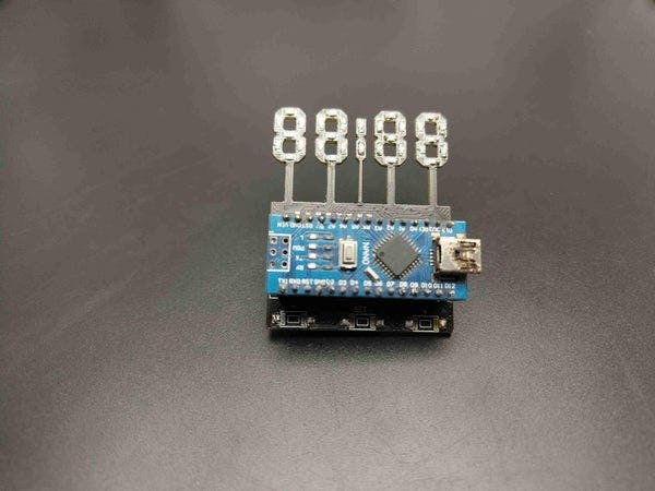
After that, I placed the populated PCB on the hot plate and cooked the PCB. I repeated the same steps for the LEDs and finished the SMD soldering.
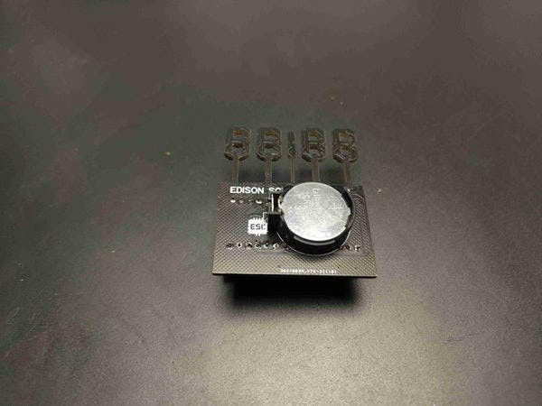
Now, I placed and soldered other THT components. first I placed the RTC crystal and soldered after that I soldered the female 2.54 pitched header pins for Arduino and the battery holder. I connected the switches through wires and soldered them to the pad. after the soldering job, our PCBs look something like this.
Arduino Programming of Skelton Clockhere I am explaining the code structure and you can download the complete code from below
#include <Wire.h>
#include "RTClib.h"
first I included the necessary header files for easy coding. I added the RTClib library for rtc communication and the Wire library for I2C communication you can download these libraries from Arduino ide just follow this path sketch-include libraries-manage libraries
int digit1 = 11; //PWM Display pin 12 (digit1 is common anonds A1 from right side)
int digit2 = 10; //PWM Display pin 9 (digit2 is  common A2)
int digit3 = 9; //PWM Display pin 8 (digit3 is common anods A3)
int digit4 = 6; //PWM Display pin 6 (digit4 is common anods, from left side)
int segA = 2; //Display pin 11
int segB = 3; //Display pin 7
int segC = 4; //Display pin 4
int segD = 5; //Display pin 2
int segE = 12; //Display pin 1
int segF = 7; //Display pin 10
int segG = 8; //Display pin 5
int segDP = 13; // Display pin 3
int pin = 1;
RTC_DS1307 RTC;
byte SW0 = A0;
byte SW1 = A1;
byte SW2 = A2;
then I defined the pins for each segment and buttons also defined the RTC module.
Wire.begin();
 RTC.begin();

 pinMode(segA, OUTPUT);
 pinMode(segB, OUTPUT);
 pinMode(segC, OUTPUT);
 pinMode(segD, OUTPUT);
in the setup section, I started the i2c communication and rtc communication and also declared the pins are segment pins as output and button pins are input.
DateTime now = RTC.now();
int timp = now.hour()*100+now.minute();
in the loop section first I read the rtc data and send it to the display. also, I used switch statements to display each digit. that's it.
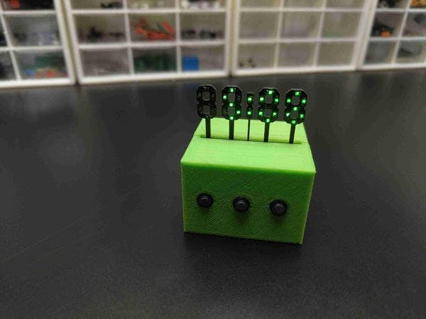
Now, let's connect the Arduino to the computer and upload the clock code. Here is the code. You can download the code and circuit diagram from my website. Links are given in the description. After uploading the code, you can see it working.
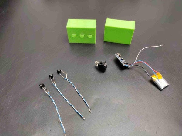
3D Printed Enclosure
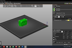
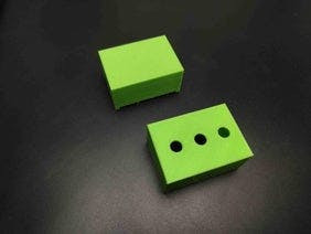
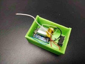
Now, the final step is to add an enclosure to the clock circuit. So, I designed a case in TinkerCAD and 3D printed it using my Ender 3V2. after printing the enclosure I placed the PCB inside the enclosure and I attached the switches to the corresponding holes.
download the 3d file from here
So, that's all about how I made this new style of skeleton clock. I hope you enjoyed it and learned something new from this tutorial. thank you
Complete making videoSchematics, diagrams and documents
CAD, enclosures and custom parts
Code
Credits
Related products


Leave your feedback...