
Arduino Nano: Flame Sensor With Visuino

Made by Ron / Home Automation / Security / Sensors
About the project
Connect Infrared Flame Sensor to Arduino, and program it to detect flames in different ways - Quick and Easy!
Project info
Difficulty: Easy
Estimated time: 1 hour
License: GNU General Public License, version 3 or later (GPL3+)
Items used in this project

Software apps and online services
Story
Recently somebody asked for tutorial on Infrared Flame Sensor. It took a while due to severe work overload, but finally I succeeded to make it.
The Infrared flame sensors use infrared light to detect flame. While experimenting with my one I discovered that in direct daylight they don't work very well due to the infrared component in the daylight. In shadow or at night my one worked quite well. The module that I have has both analog and digital output from a built in comparator.
In this tutorial, I will show you how easy it is to connect the Infrared Flame Sensor module to Arduino Nano, and program it with Visuino, to read the values from the sensor, and detect flame.
Step 1: Components
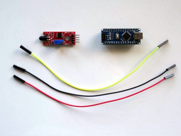
- One Arduino compatible board (I use Arduino Nano, because I have one, but any other will be just fine)
- One Flame Sensor module (I got my one from this cheap 37 sensors set ).
- 3 Female-Female jumper wires
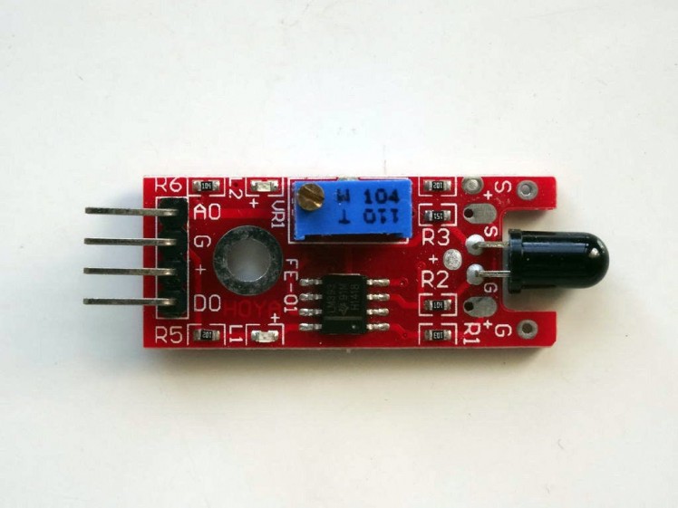
The Flame Sensor Module has built in LM393 comparator and has both Digital (DO on the Picture) and Analog (AO on the Picture) outputs. It also has a potentiometer that can be used to control the trigger level for the Digital Output.
You can use either the Analog or the Digital output in your projects.
The element on the right on the picture that looks like LED is the infrared flame sensor itself. It detects heat when the heat is placed at front of it (At front of the rounded end.)
Step 3: Connect the Flame Sensor to the Analog 0 pin of Arduino
1 / 3 • Picture 1

Picture 1

Picture 2

Picture 3
- Connect Ground(Black wire), and Power(Red wire) to the Flame Sensor Module (Picture 1)
- Connect Signal(Yellow wire) to the Analog Pin (AO) of the Flame Sensor Module (Picture 1)
- Connect the other end of the Ground wire(Black wire) to the Ground pin of the Arduino board (Picture 2)
- Connect the other end of the Power wire(Red wire) to the 5V power pin of the Arduino board (Picture 2)
- Connect the other end of the Signal wire(Yellow wire) to the Analog pin 0 of the Arduino board (Picture 2)
- Picture 3 shows where are the Ground, 5V Power, and Analog 0 pins of the Arduino Nano
1 / 2 • Picture 1

Picture 1

Picture 2
To start programming the Arduino, you will need to have the Arduino IDE installed from here: http://www.arduino.cc/ .
Make sure that you install 1.6.7 or higher, otherwise this Tutorial will not work!
The Visuino: https://www.visuino.com also needs to be installed.
- Start Visuino as shown in the first picture
- Click on the "Tools" button on the Arduino component (Picture 1) in Visuino
- When the dialog appears, select "Arduino Nano" as shown on Picture 2
1 / 2 • Picture 1

Picture 1

Picture 2
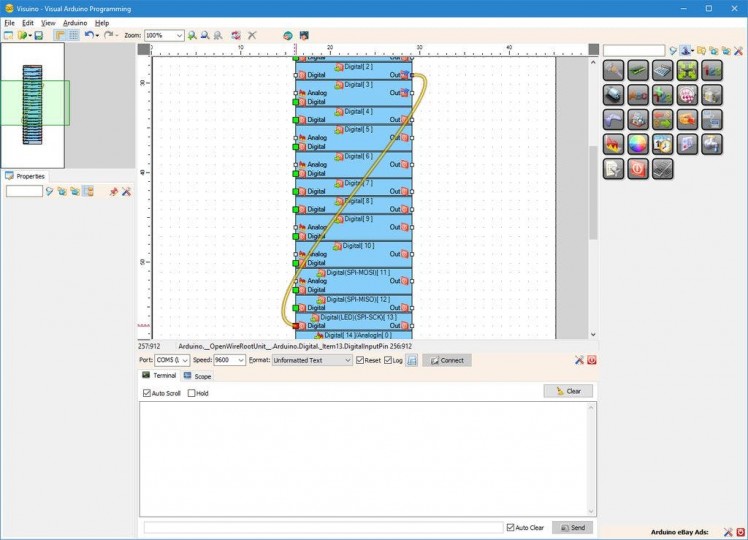
In Visuino connect the "Out" pin of the Digital[ 14 ]/Analog[ 0 ] channel of the Arduino component (Picture 1) to the "In" input pin of the Serial[ 0 ] channel of the Arduino component (Picture 2)
Step 6: Generate, Compile, and Upload the Arduino code
1 / 2 • Picture 1

Picture 1

Picture 2
- In Visuino, Press F9 or click on the button shown on Picture 1 to generate the Arduino code, and open the Arduino IDE
- In the Arduino IDE, click on the Upload button, to compile and upload the code (Picture 2)
1 / 5 • Picture 1

Picture 1

Picture 2

Picture 3

Picture 4

Picture 5
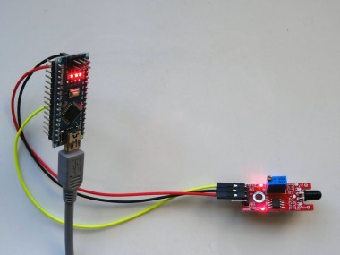
- Picture 1 shows the running project.
- Picture 2 shows the complete Visuino diagram.
In Visuino, select the serial port and click on the Connect button (Picture 3) . You should see the value of the Flame Sensor output printed on the Serial terminal (Picture 4)
If you switch to the Scope tab, you will see the data from the sensor plotted on the scope (Picture 5)
If exposed to direct daylight, or other source of heat, the sensor will react to it as a flame. If the sensor is not exposed to direct source of heat, the sensor will send values close to 1.0. If you point it to a flame, the analog values will drop close to 0.0 .
You can also see this on the Video.
Also attached is the Visuino project, that I created for this Tutorial. You can download and open it in Visuino: https://www.visuino.com
Step 8: In Visuino: Add and connect Compare Analog Value component
1 / 5 • Picture 1

Picture 1

Picture 2

Picture 3

Picture 4

Picture 5
To use the analog value as digital ON/OFF "Detected Flame" signal, you will need to convert it to digital boolean value. There are many ways in which this can be done. One of them is to use Compare Analog Value component and compare the signal to a value:
- Type "compare" in the Filter box of the Component Toolbox then select the "Compare Analog Value" component (Picture 1), and drop it in the design area
- Connect the "Out" pin of the "Digital[ 14 ]/Analog[ 0 ]" channel of the Arduino component to the "In" pin of the CompareAnalogValue1 component (Picture 2)
- Connect the "Out" pin of the CompareAnalogValue1 component to the "Digital" input pin of the "Digital[ 13 ]" channel of the Arduino component (Picture 3)
- In the Object Inspector, set the value of the "Compare Type" property of the CompareAnalogValue1 component to ctSmaller (Picture 4)
- In the Object Inspector, set the value of the "Value" property of the CompareAnalogValue1 component to 0.5 (Picture 5)
1 / 3 • Picture 1

Picture 1

Picture 2

Picture 3
- Generate, Compile, and Upload the Arduino code as you did in Step 6
- If there is no heat source at front of the sensor he LED on pin 13 will be off (Picture 2)
- If you place a heat source (flame) at front of the sensor, the LED on pin 13 will turn on (Picture 3)
On Picture 1 you can see the complete Visuino diagram.
You can also see the sensor in action on the Video.
Also attached is the Visuino project, that I created for this Tutorial. You can download and open it in Visuino: https://www.visuino.com
Step 10: In Visuino: Add and connect Schmitt Trigger component
1 / 4 • Picture 1

Picture 1

Picture 2

Picture 3

Picture 4
Another way to convert the analog value while reducing noise during the switching is to use Schmitt Trigger component with Hysteresis:
- Start with the original project where just the Analog 0 was connected to the Serial port.
- Type "schm" in the Filter box of the Component Toolbox then select the "Analog Schmitt Trigger (Hysteresis)" component (Picture 1), and drop it in the design area
- Connect the "Out" pin of the "Digital[ 14 ]/Analog[ 0 ]" channel of the Arduino component to the "In" pin of the SchmittTrigger1 component (Picture 2)
- Connect the "Out" pin of the SchmittTrigger1 component to the "Digital" input pin of the "Digital[ 13 ]" channel of the Arduino component (Picture 3)
- In the Object Inspector set the value of the "Inverted" property of the SchmittTrigger1 component to "True" (Picture 4)
- Optionally, in the Object Inspector, change the values of the "Threshold" and the "Value" properties of the SchmittTrigger1 component
1 / 3 • Picture 1

Picture 1

Picture 2

Picture 3
- Generate, Compile, and Upload the Arduino code as you did in Step 6
- If there is no heat source at front of the sensor he LED on pin 13 will be off (Picture 2)
- If you place a heat source (flame) at front of the sensor, the LED on pin 13 will turn on (Picture 3)
On Picture 1 you can see the complete Visuino diagram.
You can also see the sensor in action on the Video.
Also attached is the Visuino project, that I created for this Tutorial. You can download and open it in Visuino: https://www.visuino.com
Step 12: Connect the Flame Sensor to the Digital 2 pin of Arduino
1 / 3 • Picture 1

Picture 1

Picture 2

Picture 3
The Flame Sensor can also be connected to a Digital Pin instead of analog pin.
- Disconnect the Signal wire(Yellow wire) from the Analog (AO)pin of the Flame Sensor and connect it to the Digital (DO) pin of the Flame Sensor (Picture 1)
- Disconnect the Signal wire(Yellow wire) from the Analog 0 pin of the Arduino board and connect it to the Digital pin 2 of the Arduino board (Picture 2)
- Picture 3 shows where are the Ground, 5V Power(In Blue), and Digital 2(In Red) pins of the Arduino Nano
- Start a new Visuino project and select Board type as "Arduino Nano" as you did in Step 4
- In Visuino connect the "Out" pin of the "Digital[ 2 ]" channel of the Arduino component to the "Digital" input pin of the "Digital[ 13 ]" channel of the Arduino component (as shown on the Picture)
1 / 3 • Picture 1

Picture 1

Picture 2

Picture 3
- Generate, Compile, and Upload the Arduino code as you did in Step 6
- If there is no heat source at front of the sensor he LED on pin 13 will be off (Picture 2)
- If you place a heat source (flame) at front of the sensor, the LED on pin 13 will turn on (Picture 3)
On Picture 1 you can see the complete Visuino diagram.
You can also see the sensor in action on the Video.
If necessary, you can use the Potentiometer on the Flame Sensor Module to adjust the level when the flame is detected.
Also attached is the Visuino project, that I created for this Tutorial. You can download and open it in Visuino: https://www.visuino.com
Credits
Related products


Leave your feedback...