
Arduino Nano: Control 2 Stepper Motors With Joystick

Made by Ron / Home Automation / Robotics / Sensors
About the project
Connect 2 Stepper Motors to Arduino and control them with Joystick - Quick and Easy!
Project info
Difficulty: Easy
Estimated time: 1 hour
License: GNU General Public License, version 3 or later (GPL3+)
Items used in this project
Hardware components

Software apps and online services
Story
When building Arduino projects with Stepper motors, such as CNC machine, plotter, or Animated Art, there comes a moment when the steppers need to be controlled manually. Analog Joysticks are cheap and easy modules for manual control, with variable speed. They seem to be a good choice to control the steppers. Solving the problem with traditional Arduino code however is not trivial.
In this Tutorial, I will show you how easy it is to program Arduino Nano with Visuino to control 2 stepper motors with Joystick.
Step 1: Components
1 / 2 • Picture 1

Picture 1

Picture 2
- One Arduino compatible board (I use Arduino Nano, because I have one, but any other will be just fine)
- One Joystick that I got from this cheap 37 sensors set
- Two 5V Stepper Motors with Driver Boards (I used 28BYJ-48 stepper with ULN2003 driver board )
- One K2 Breadboard power supply with adapter (Picture 2), or other 5V Power source for the Steppers
- 17 Female-Female jumper wires
1 / 6 • Picture 1

Picture 1

Picture 2

Picture 3

Picture 4

Picture 5

Picture 6
- Connect Ground(Black wire), and Power(Red wire), to each of the Stepper Driver modules (Picture 1)
- Connect another Ground(Black wire) to Ground pin of the Arduino board (Picture 2)
- Connect the other end of the Power (Red wires) from the Motor Driver modules to the "" Power pins of the K2 Power supply (Pictures 3, and 4)
- Connect the other end of the Ground (Black wires) from the Motor Driver modules, and the Arduino to the "-" Ground pins of the K2 Power supply (Pictures 3, and 4)
- Make sure the Power Selection Switch of the K2 power supply is set to 5V (Picture 5)
- Picture 6 shows where is the Ground pin of the Arduino Nano
1 / 4 • Picture 1

Picture 1

Picture 2

Picture 3

Picture 4
- If not already connected, plug the Stepper Motor connectors into the Driver Boards
- Connect one end of Female-Female jumper wires (Blue, Green, Yellow and Orange wires) to the IN1 to IN4 pins of the Stepper Driver for the First Motor (Picture 1)
- Connect one end of Female-Female jumper wires (Blue, Green, Yellow and Orange wires) to the IN1 to IN4 pins of the Stepper Driver for the Second Motor (Picture 1)
- Connect the IN1 wire from the First Motor (Blue wire) to the Digital pin 2 of the Arduino board (Picture 2)
- Connect the IN2 wire from the First Motor (Green wire) to the Digital pin 3 of the Arduino board (Picture 2)
- Connect the IN3 wire from the First Motor (Yellow wire) to the Digital pin 4 of the Arduino board (Picture 2)
- Connect the IN4 wire from the First Motor (Orange wire) to the Digital pin 5 of the Arduino board (Picture 2)
- Connect the IN1 wire from the Second Motor (Blue wire) to the Digital pin 6 of the Arduino board (Picture 3)
- Connect the IN2 wire from the Second Motor (Green wire) to the Digital pin 7 of the Arduino board (Picture 3)
- Connect the IN3 wire from the Second Motor (Yellow wire) to the Digital pin 8 of the Arduino board (Picture 3)
- Connect the IN4 wire from the Second Motor (Orange wire) to the Digital pin 9 of the Arduino board (Picture 3)
- Picture 4 shows in Red where are the Digital 2 to Digital 9 pins of the Arduino Nano . In Blue is shown the connection done in the previous step.
1 / 4 • Picture 1

Picture 1

Picture 2

Picture 3

Picture 4
- Connect Female-Female wires to the Ground(Black wire), Power(Red wire), VRx(Purple wire), and VRy(Gray wire) of the Joystick as shown in Picture 1
- Connect the Ground wire(Black wire) to the Ground pin of the Arduino board (Picture 2)
- Connect the Power wire(Red wire) to the 5V Power pin of the Arduino (Picture 2)
- Connect the VRx wire(Brown wire) the the Analog 1 pin of the Arduino board (Picture 3)
- Connect the VRy wire(Gray wire) the the Analog 0 pin of the Arduino board (Picture 3)
- Picture 4 shows in Red where are the Ground, 5V Power, Analog 0, and Analog 1 pins of the Arduino Nano . In Blue is shown the connection done in the previous steps.
1 / 2 • Picture 1

Picture 1

Picture 2
To start programming the Arduino, you will need to have the Arduino IDE installed from here: http://www.arduino.cc/ .
Make sure that you install 1.6.7 higher, otherwise this Tutorial will not work!
The Visuino: https://www.visuino.com also needs to be installed.
- Start Visuino as shown in the first picture
- Click on the "Tools" button on the Arduino component (Picture 1) in Visuino
- When the dialog appears, select Arduino Nano as shown in Picture 2
1 / 3 • Picture 1

Picture 1

Picture 2

Picture 3
First we need to add components to control the stepper motors:
- Type "step" in the Filter box of the Component Toolbox then select the "4 Wire Stepper Motor" component (Picture 1), and drop two of them it in the design area
- Click in the "Out" box containing the pins of the Stepper1 component to start connecting all the Out pins at once (Picture 2)
- Move the mouse over the "Digital" input pin of the "Digital[ 2 ]" channel of the Arduino component. The Visuino will automatically spread the wires so they will connect correctly to the rest of the pins (Picture 2)
- Click in the "Out" box containing the pins of the Stepper2 component to start connecting all the Out pins at once (Picture 3)
- Move the mouse over the "Digital" input pin of the "Digital[ 6 ]" channel of the Arduino component. The Visuino will automatically spread the wires so they will connect correctly to the rest of the pins (Picture 3)
1 / 4 • Picture 1

Picture 1

Picture 2

Picture 3

Picture 4
Since we want to control the speed of the steppers, we need to add pins to the "Steps Per Second" property:
- Select the Stepper1 component (Picture 1)
- In the Object Inspector, set the value of the "Steps Per Second" property to "0" (Picture 1)
- In the Object Inspector click on the Pin button at front of the "Steps Per Second" property, and select "Float SinkPin" (Picture 2)
- Select the Stepper2 component (Picture 3)
- In the Object Inspector, set the value of the "Steps Per Second" property to "0" (Picture 3)
- In the Object Inspector click on the Pin button at front of the "Steps Per Second" property, and select "Float SinkPin" (Picture 4)
1 / 5 • Picture 1

Picture 1

Picture 2

Picture 3

Picture 4

Picture 5
The Analog Pins where the Joystick is connected generate normalized values between 0.0 and 1.0. We need to convert them to +/-300 steps per second. Since the Joystick is not very precise when in released center position, we want a small zone around the center to be considered 0.5 so we need to introduce "Dead Zone":
- Type "zone" in the Filter box of the Component Toolbox then select the "Dead Zone Scaled Analog" component (Picture 1), and drop two of them it in the design area
- Connect the "Out" output pin of the DeadZoneScaled1 component to the "StepsPerSecond" input pin of the Stepper1 component (Picture 2)
- Connect the "Out" output pin of the "Digital[ 14 ]/Analog[ 0 ]" channel of the Arduino component to the "In" input pin of the DeadZoneScaled1 component (Picture 3)
- Connect the "Out" output pin of the DeadZoneScaled2 component to the "StepsPerSecond" input pin of the Stepper2 component (Picture 4)
- Connect the "Out" output pin of the "Digital[ 15 ]/Analog[ 1 ]" channel of the Arduino component to the "In" input pin of the DeadZoneScaled2 component (Picture 5)
1 / 4 • Picture 1

Picture 1

Picture 2

Picture 3

Picture 4
- In the Design Area, select the DeadZoneScaled1 component (Picture 1)
- In the Object Inspector, expand the "Output Range" property (Picture 1)
- In the Object Inspector, set the value of the "Max" sub-property of the "Output Range" property to "300" (Picture 1)
- In the Object Inspector, set the value of the "Min" sub-property of the "Output Range" property to "-300" (Picture 2)
- In the Design Area, select the DeadZoneScaled2 component (Picture 3)
- In the Object Inspector, expand the "Output Range" property (Picture 3)
- In the Object Inspector, set the value of the "Max" sub-property of the "Output Range" property to "300" (Picture 3)
- In the Object Inspector, set the value of the "Min" sub-property of the "Output Range" property to "-300" (Picture 4)
1 / 2 • Picture 1

Picture 1

Picture 2
- In Visuino, Press F9 or click on the button shown on Picture 1 to generate the Arduino code, and open the Arduino IDE
- In the Arduino IDE, click on the Upload button, to compile and upload the code (Picture 2)
1 / 2 • Picture 1

Picture 1

Picture 2
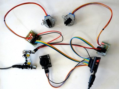
Congratulations! You have completed the project.
Picture 1 and the Video show the connected and powered up project.
You can control the Steppers with the Joystick as seen the Video. Moving the Joystick Up and Down will control the Forward and Backward rotation of one of the Steppers. Moving the Joystick Left and Right will control the other Stepper.
On Picture 2 you can see the complete Visuino diagram.
Also attached is the Visuino project, that I created for this Tutorial. You can download and open it in Visuino: https://www.visuino.com
Credits
Related products


Leave your feedback...