
Arduino Nano: Analog 7 Segment Max7219 Display With Visuino

About the project
Easily Display Analog values from Arduino to 7 Segment Display with the help of Visuino.
Project info
Difficulty: Easy
Estimated time: 1 hour
License: GNU General Public License, version 3 or later (GPL3+)
Items used in this project
Hardware components

Software apps and online services
Story
7 Segment Displays are very popular choice for displaying data. They however consist of a large number of LEDs and controlling each LED with a digital pin from Arduino is not a practical solution. Maxim Integrated offers very convenient chip for controlling large number of LEDs and 7 Segment displays - MAX7219 . There are a lot of cheap readily available 7 Segment modules using this chip.
In this Tutorial, I will show you how easy it is to connect such module to Arduino, and control it with Visuino.
Step 1: Components
1 / 2 • Picture 1

Picture 1

Picture 2
- One Arduino compatible board (I use Arduino Nano, because I have one, but any other will be just fine)
- One 8 digits 7 Segment Display module with MAX7219 controller (Picture 2 shows the back side of the module with the MAX7219 controller)
- 5 Female-Female jumper wires
1 / 5 • Picture 1

Picture 1

Picture 2

Picture 3

Picture 4

Picture 5
- Connect Power (Red wire), Ground (Black wire), DIN (Green wire), CS (White wire), and CLK (Yellow wire) to the LED Module (Picture 1)
- Connect the other end of the Power wire (Red wire) to the 5V power pin of the Arduino board (Picture 2)
- Connect the other end of the Ground wire (Black wire) to Ground pin of the Arduino board (Picture 2)
- Connect the other end of the DIN wire (Green wire) to the Digital 11 pin of the Arduino board (Picture 3)
- Connect the other end of the CS wire (White wire) to the Digital 10 pin of the Arduino board (Picture 3)
- Connect the other end of the CLK wire (Yellow wire) to the Digital 13 pin of the Arduino board (Picture 4)
- Picture 5 shows where are the Ground, 5V Power, Digital 10, 11, and 13, pins of the Arduino Nano
1 / 2 • Picture 1

Picture 1

Picture 2
To start programming the Arduino, you will need to have the Arduino IDE installed from here: http://www.arduino.cc/ .
Please be aware that there are some critical bugs in Arduino IDE 1.6.6.
Make sure that you install 1.6.7 or higher, otherwise this Tutorial will not work!
The Visuino: https://www.visuino.com also needs to be installed.
- Start Visuino as shown in the first picture
- In Visuino, click on the "Tools" button on the Arduino component (Picture 1)
- When the dialog appears, select Arduino Nano as shown in Picture 2
1 / 3 • Picture 1

Picture 1

Picture 2

Picture 3
- Type "7219" in the Filter box of the Component Toolbox then select the "Maxim Led Controller SPI MAX7219/MAX7221" component (Picture 1), and drop it in the design area
- Connect the "Out" pin of the LedController1 component to the to the "In" pin of the SPI channel of the Arduino component (Picture 2)
- Connect the "ChipSelect" pin of the LedController1 component to the "Digital" input of the "Digital[ 10 ]" channel of the Arduino component (Picture 3)
1 / 3 • Picture 1

Picture 1

Picture 2

Picture 3
The LedController1 component can control LEDs in many different ways. How the LEDs are organized and controlled depends on what Elements will be added to the component. Here we will add just one element to control the 7 Segment display with Analog value.
- Click on the "Tools" button of the LedController1 component(Picture 1)
- In the Elements editor, double-click on the "Analog Display 7 Segments" to add one to the component (Picture 2)
- In the Object Inspector, set the value of the "Precision" property of the newly added "Analog Display 7 Segments1" element to 7 (Picture 3)
1 / 3 • Picture 1

Picture 1

Picture 2

Picture 3
We need to send some Analog values to be displayed. The simplest option is to use a Random generator to generate values for the display. We will set the generator to generate a random number between 0 and 100:
- Type "rand" in the Filter box of the Component Toolbox then select the "Random Analog Generator" component (Picture 1), and drop it in the design area
- In the Object Inspector, set the value of the "Max" property of the RandomAnalogGenerator1 to 100 (Picture 2)
- Connect the "Out" pin of the RandomAnalogGenerator1 component to the to the "In" pin of the LedController1 component(Picture 3)
1 / 3 • Picture 1

Picture 1

Picture 2

Picture 3
We can use the project as designed up to this point, but the Analog value for the Display will change too fast, and it will be difficult to read the display. For this we will add a Clock Generator and set it to clock 5 times a second. The clock generator will clock the Random generator to generate a new value 5 times a second:
- Type "clock" in the Filter box of the Component Toolbox then select the "Clock Generator" component (Picture 1), and drop it in the design area
- Connect the "Out" pin of the ClockGenerator1 component to the to the "Clock" pin of the RandomAnalogGenerator1 component (Picture 2)
- In the Object Inspector, set the value of the "Frequency" property of the ClockGenerator1 to 5 (Picture 3)
1 / 2 • Picture 1

Picture 1

Picture 2
- In Visuino, Press F9 or click on the button shown on Picture 1 to generate the Arduino code, and open the Arduino IDE
- In the Arduino IDE, click on the Upload button, to compile and upload the code (Picture 2)
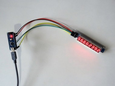
1 / 2 • Picture 1

Picture 1

Picture 2
Congratulations! You have completed the project.
Picture 1 shows the connected and powered up project. You should see the random analog values being displayed on the 7 Segment display.
You can play with some of the properties we set in the Tutorial, to adjust how often the display is refreshed, the minimum, and maximum numbers generated, and the floating point precision.
On Picture 2 you can see the complete Visuino diagram.
Also attached is the Visuino project, that I created for this Tutorial. You can download and open it in Visuino: https://www.visuino.com
Credits
Related products


Leave your feedback...