
Arduino Digital Compass Using Mpu9250 Magnetometer

About the project
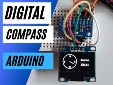
In this project we will learn how to make a compass using the Arduino and the Accelerometer Gyroscope sensor MPU9250. Watch the Video!
Project info
Difficulty: Easy
Estimated time: 1 hour
License: GNU General Public License, version 3 or later (GPL3+)
Items used in this project
Hardware components

Story
In this project we will learn how to make a compass using the Arduino and the Accelerometer Gyroscope sensor MPU9250.
Watch the Video!
Step 1: What You Will Need
1 / 5
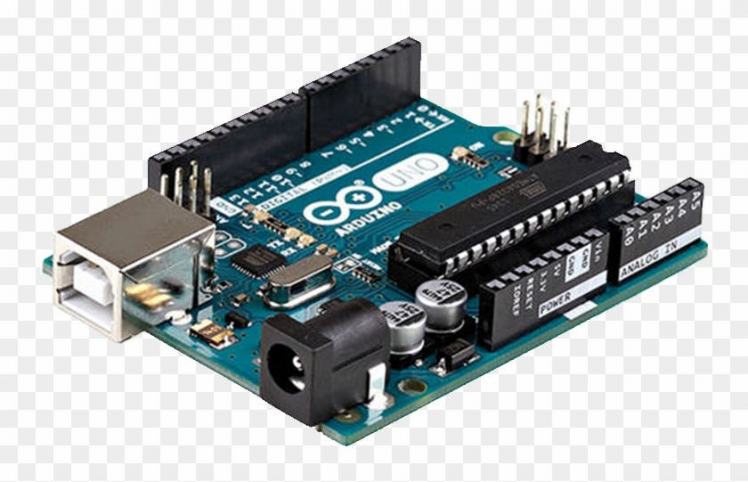
- Arduino UNO (or any other Arduino)
- MPU9250 (is an accelerometer, gyroscope, magnetometer sensor)
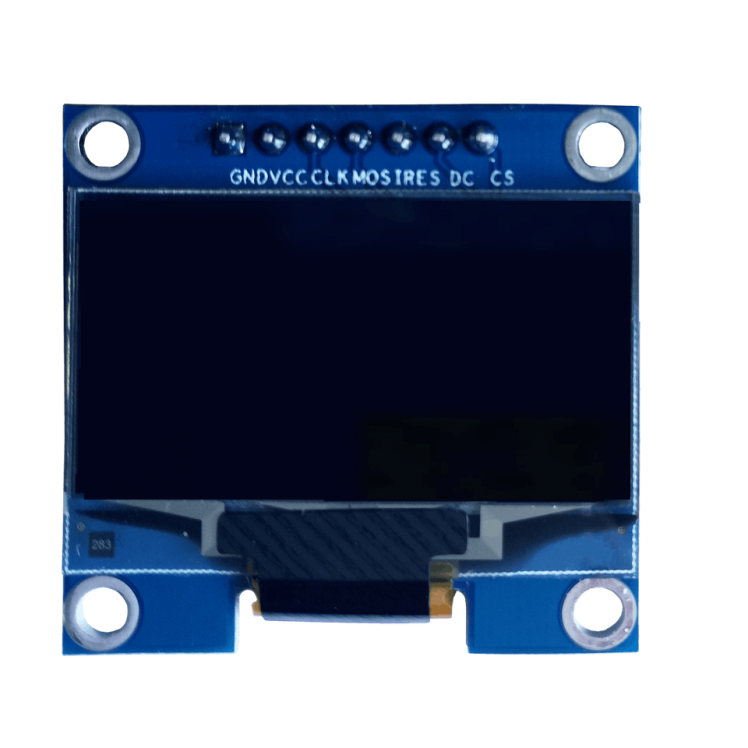
- OLED I2C Display
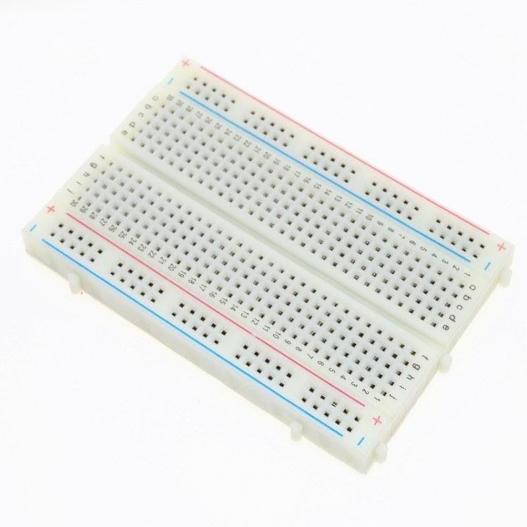
- Breadboard
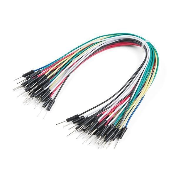
- Jumper wires
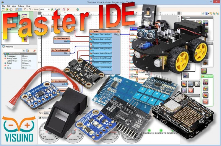
- Visuino program: Download Visuino
Step 2: The Circuit
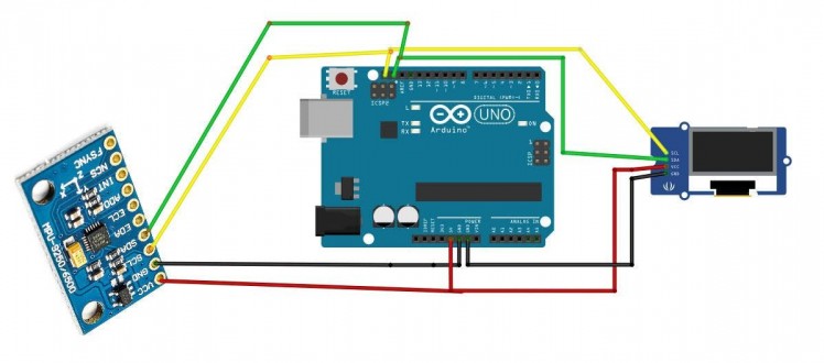
- Connect OLED Display pin [SCL] to Arduino pin [SCL]
- Connect OLED Display pin [SDA] to Arduino pin [SDA]
- Connect OLED Display pin [VCC] to Arduino pin [5v]
- Connect OLED Display pin [GND] to Arduino pin [GND]
- Connect MPU9250 Sensor pin [SCL] to Arduino pin [SCL]
- Connect MPU9250 Sensor pin [SDA] to Arduino pin [SDA]
- Connect MPU9250 Sensor pin [VCC] to Arduino pin [5v]
- Connect MPU9250 Sensor pin [GND] to Arduino pin [GND]
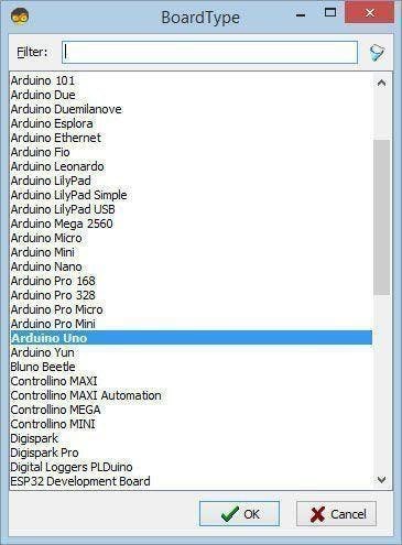
Step 3: Start Visuino, and Select the Arduino UNO Board Type
1 / 2
The Visuino: https://www.visuino.eu also needs to be installed. Download Free version or register for a Free Trial.
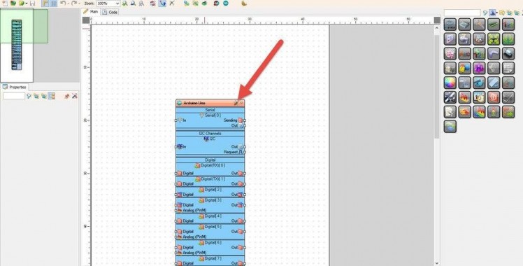
Start Visuino as shown in the first picture Click on the "Tools" button on the Arduino component (Picture 1) in Visuino When the dialog appears, select "Arduino UNO" as shown on Picture 2
Step 4: In Visuino Add Components
1 / 5
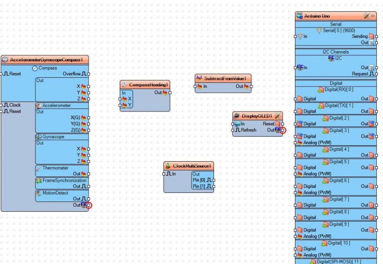
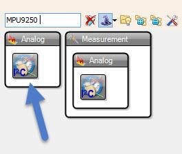
- Add "Accelerometer Gyroscope Compass MPU9250 I2C" component
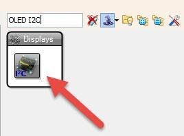
- Add "OLED I2C" component
- Add "Compass Heading" component
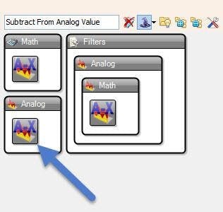
- Add "Subtract From Analog Value" component
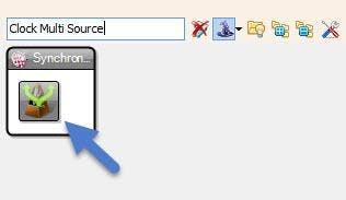
- Add "Clock Multi Source" component
Step 5: In Visuino Set Components
1 / 6

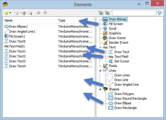
Double click on the "DisplayOLED1" and in the Elements window:
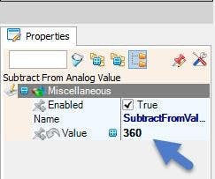
- Select "SubtractFromValue1" and in the Properties window set the Value to 360
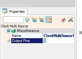
- Select "ClockMultiSource1" and in the Properties window set Output Pins to 9
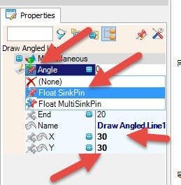
Drag "Draw Angled Line" to the left side and in the properties window set "X" to 30 and "Y " to 30Click on the "Angle" Pin Icon and select "Float SinkPin"
- Drag "Draw Ellipse" to the Left side and in the properties window set "Height" to 58 and "Width" to 62
Add 5X "Draw Text" to the left side
- Select "Draw Text1" and in the Properties window set "Text" to N set "X" to 50 and "Y " to 28
- Select "Draw Text4" and in the Properties window set "Text" to E set "X" to 30 and "Y " to 50
- Select "Draw Text5" and in the Properties window set "Text" to Degreeset "X" to 80 and "Y " to 20
- Select "Draw Text3" and in the Properties window set "Text" to S set "X" to 5 and "Y " to 28
- Select "Draw Text2" and in the Properties window set "Text" to W set "X" to 30 and "Y " to 5
- Add "Fill Screen" to the left side
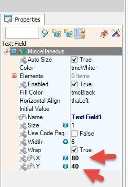
- Add "Text Field" to the left side and in the properties window set "X" to 80 and "Y " to 40
Step 6: In Visuino Connect Components
1 / 3
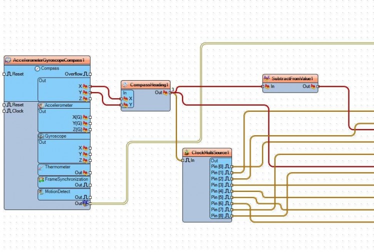

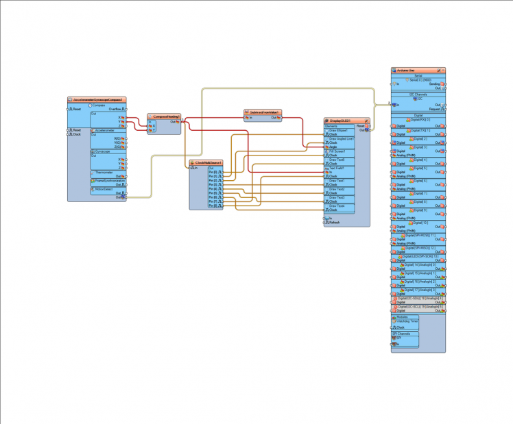
- Connect "AccelerometerGyroscopeCompass1" Compass Pin [X] and Pin [Y] to "CompassHeading1" Pin [X] and Pin [Y]
- Connect "CompassHeading1" Pin [Out] to "ClockMultiSource1" Pin [In]
- Connect "CompassHeading1" to "SubtractFromValue1" Pin [In], and to "DisplayOLED1" > Text Field1 Pin [In]
- Connect "SubtractFromValue1" Pin [Out] to "DisplayOLED1" > Draw Angled Line1 Pin [Angle]
- Connect "ClockMultiSource1" Pin [0] to "DisplayOLED1" Fill Screen1 Pin [Clock]
- Connect "ClockMultiSource1" Pin [1] to "DisplayOLED1" Draw Ellipse1 Pin [Clock]
- Connect "ClockMultiSource1" Pin [2] to "DisplayOLED1" Draw Angled Line1 Pin [Clock]
- Connect "ClockMultiSource1" Pin [3] to "DisplayOLED1" Draw Text1 Pin [Clock]
- Connect "ClockMultiSource1" Pin [4] to "DisplayOLED1" Draw Text2 Pin [Clock]
- Connect "ClockMultiSource1" Pin [5] to "DisplayOLED1" Draw Text3 Pin [Clock]
- Connect "ClockMultiSource1" Pin [6] to "DisplayOLED1" Draw Text4 Pin [Clock]
- Connect "ClockMultiSource1" Pin [7] to "DisplayOLED1" Draw Text5 Pin [Clock]
- Connect "ClockMultiSource1" Pin [8] to "DisplayOLED1" Text Field1 Pin [Clock]
- Connect "AccelerometerGyroscopeCompass1" Pin I2C [Out] to Arduino board pin I2C [In]
- Connect "DisplayOLED1 " Pin I2C [Out] to Arduino board pin I2C [In]
Step 7: Generate, Compile, and Upload the Arduino Code
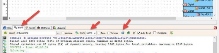
In Visuino, at the bottom click on the "Build" Tab, make sure the correct port is selected, then click on the "Compile/Build and Upload" button.
Step 8: Play
If you power the Arduino module, the OLED Display will start to show the compass direction and current degree.
Congratulations! You have completed your project with Visuino. Also attached is the Visuino project, that I created for this Tutorial, you can download it and open it in Visuino: https://www.visuino.eu
Schematics, diagrams and documents
Code
Credits
Related products


Leave your feedback...