
Arduino Countdown Timer With Relay

About the project
In this tutorial we will learn how to make a Countdown Timer, you can set time When timer reaches the zero the Relay will trigger the light.
Project info
Difficulty: Easy
Estimated time: 1 hour
License: GNU General Public License, version 3 or later (GPL3+)
Items used in this project
Hardware components

Story
In this tutorial we will learn how to make a Countdown Timer, where you can set time with one button and start the timer with another button. When timer reaches the zero the Relay will trigger the lamp to turn it On.
Watch the Video!
Step 1: What Will You Need
1 / 8
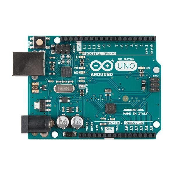
- Arduino UNO (or any other board)
- LED Display TM1637
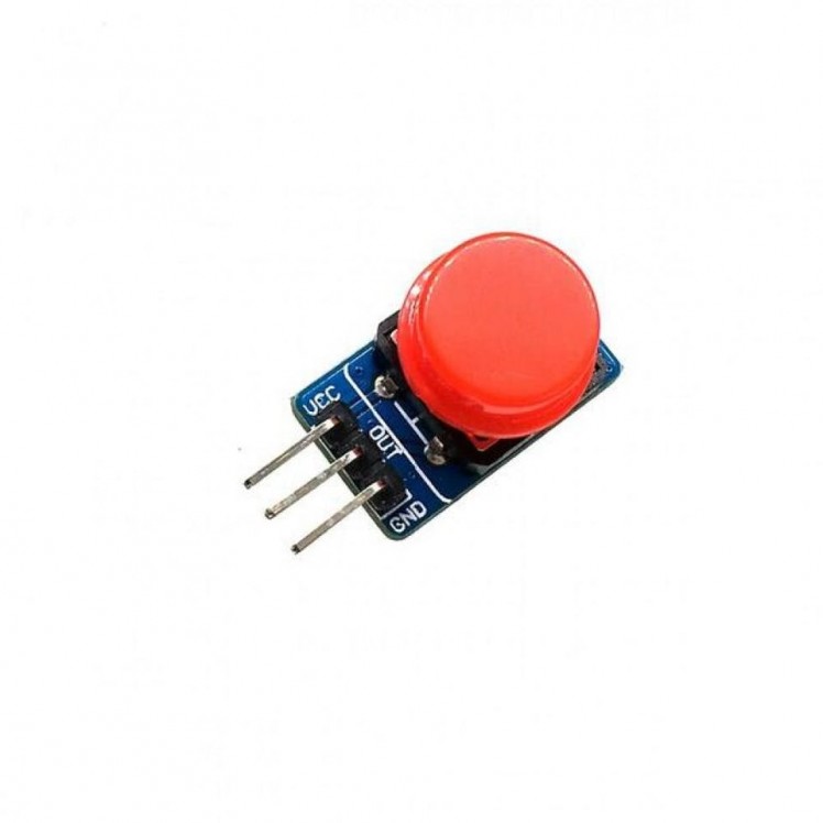
- 2X button modules
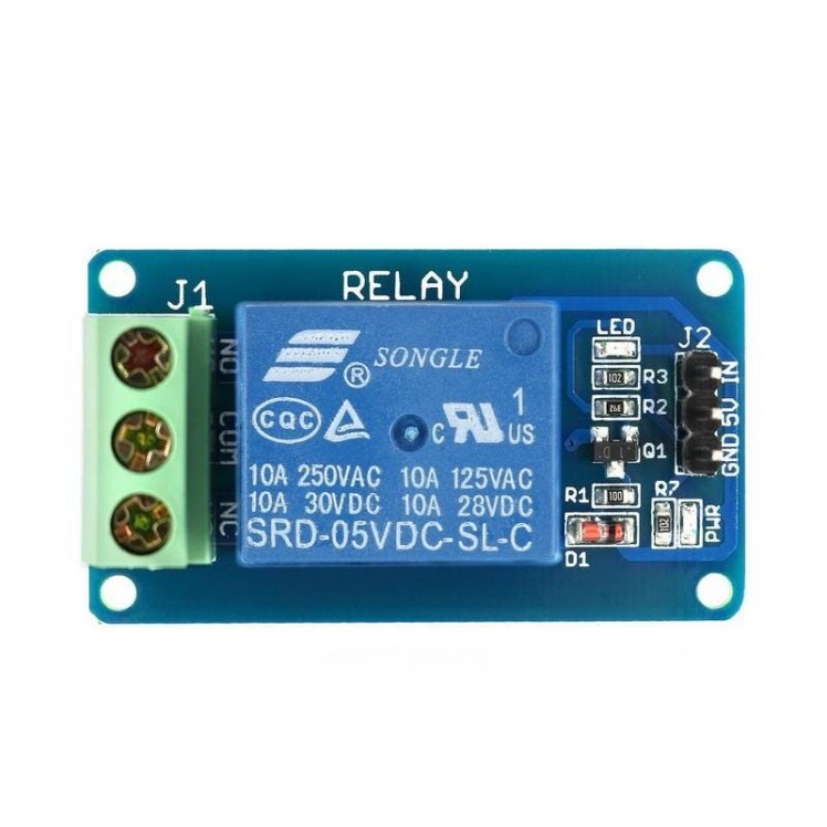
- Relay module
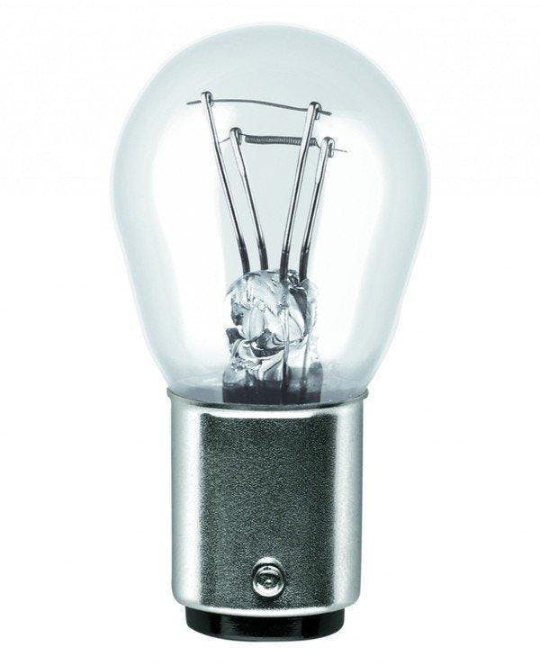
- 12V light bulb
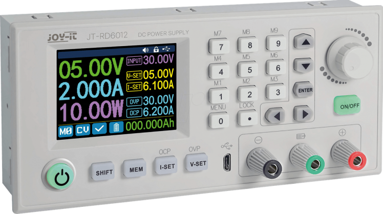
- 12V power supply
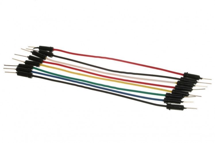
- Jumper wires
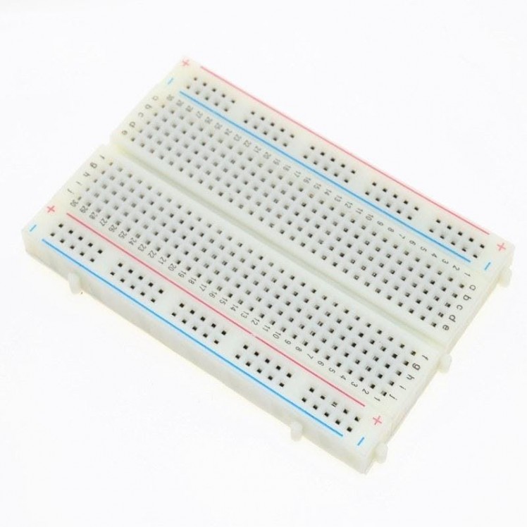
- Breadboard
- Visuino program: Download Visuino
Step 2: The Circuit
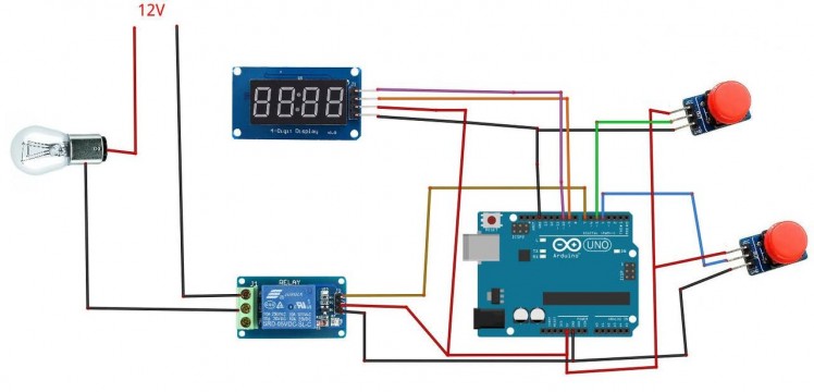
- Connect LED Display pin[CLK] to Arduino digital pin[10]
- Connect LED Display pin[DI0] to Arduino digital pin[9]
- Connect LED Display pin[GND] to Arduino pin[GND]
- Connect LED Display pin[VCC] to Arduino pin[5V]
- Connect button module1 and button module2 pin [Vcc] to Arduino pin [5V]
- Connect button module1 and button module2 pin [GND] to Arduino pin [GND]
- Connect button module1 pin [Out] to Arduino digital pin [4]
- Connect button module2 pin [Out] to Arduino digital pin [5]
- Connect Relay VCC pin(+) to Arduino 5V pin
- Connect Relay GND pin(-) to Arduino GND pin
- Connect Relay signal pin(S) to Arduino Digital pin [7]
- Connect power supply 12V (+) to the Lamp positive (+)
- Connect power supply 12V (-) to the relay pin (NO)
- Connect Lamp negative (-) to relay pin(com)
Step 3: Start Visuino, and Select the Arduino UNO Board Type
1 / 2
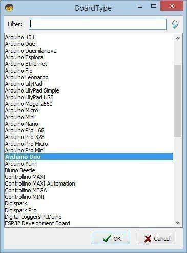
The Visuino: https://www.visuino.eu also needs to be installed. Download Free version or register for a Free Trial.
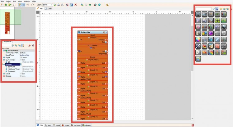
Start Visuino as shown in the first picture Click on the "Tools" button on the Arduino component (Picture 1) in Visuino When the dialog appears, select "Arduino UNO" as shown on Picture 2
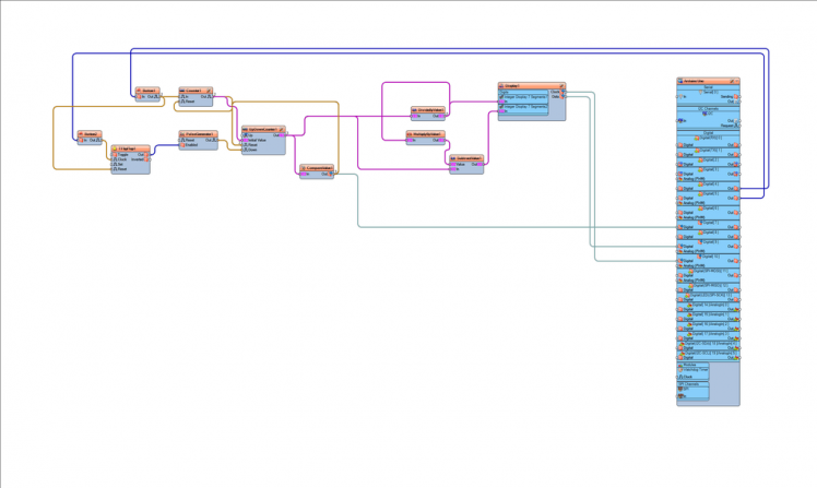
Step 4: In Visuino Add Components
1 / 10


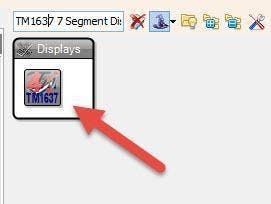
- Add "TM1637 7 Segment Display 4 Digits Module + 2 Vertical Points (CATALEX)" component
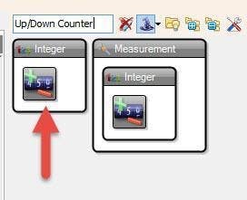
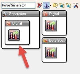
- Add "Up/Down Counter" componentAdd "Pulse generator" component
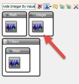
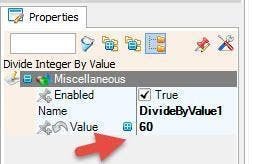
- Add "Divide Integer By Value" component
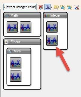
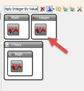
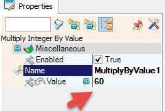
- Add "Multiply Integer By Value" componentAdd "Subtract Integer Value" component
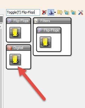
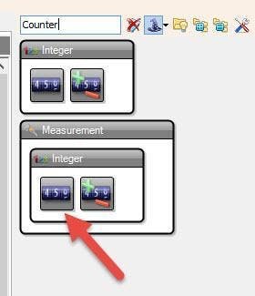
- Add "Counter" componentAdd "Toggle(T) Flip-Flop" component
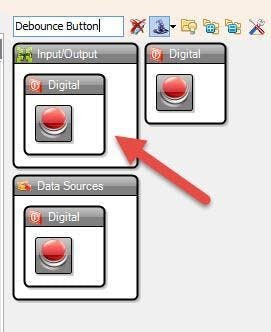
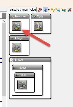
- Add 2X "Debounce button" componentsAdd "Compare Integer Value" component
Step 5: In Visuino Set Components
1 / 9
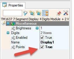

- Select "Display1" and in the properties window set "Points" to True
- Double click on "Display1" component and in the "Digits" window
- drag "Integer Display 7 Segments" to the left side
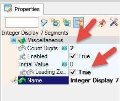
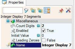
- On the left side of the "Digits" window select "Integer Display 7 Segments1" and in the properties window set "Count Digits" to 2
- drag another "Integer Display 7 Segments" to the left side
- On the left side of the "Digits" window select "Integer Display 7 Segments2" and in the properties window set "Count Digits" to 2 and "Leading Zeroes" to True
- Close the "Digits" window
- Select "UpDownCounter1" and in the properties window select:"Initial Value" and click on the pin icon and select "Integer SinkPin"Max > Roll Over" to False"Min > Roll Over" to Falseand Min Value to 0.
- Select "DivideByValue1" and in the properties window set Value to 60
- Select "MultiplyByValue1" and in the properties window set Value to 60
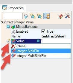
- Select "SubtractValue1" and in the properties window select Value and click on the Pin Icon and select "Integer SinkPin"
- Select "PulseGenerator1" and in the properties window
- Select "Enabled" and click on the pin icon and select "Boolean SinkPin" and set "Enabled" to False
Step 6: In Visuino Connect Components
1 / 5
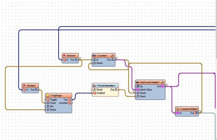
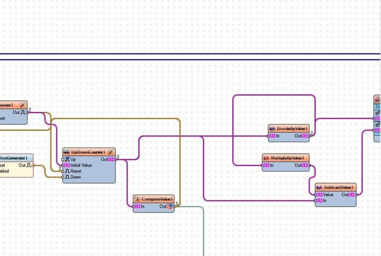
- Connect "PulseGenerator1" pin Out to "UpDownCounter1" pin Down
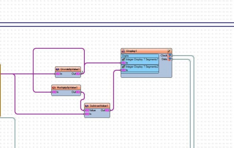
- Connect "UpDownCounter1" pin Out to "DivideByValue1" pin In and "SubtractValue1" pin In
- Connect "DivideByValue1" pin Out to "MultiplyByValue1" pin In and "Display1" > "Integer Display 7 Segments1" pin In
- Connect "MultiplyByValue1" pin Out to "SubtractValue1" pin Value
- Connect "SubtractValue1' pin Out to "Display1" > "Integer Display 7 Segments2" pin In
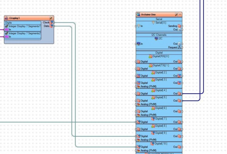
- Connect "Display1" pin Clock to Arduino digital pin 10
- Connect "Display1" pin Data to Arduino digital pin 9
- Connect Arduino digital Out pin [4] to "Button1" pin [In]
- Connect Arduino digital Out pin [5] to "Button2" pin [In]
- Connect "Button1" pin[Out] to "Counter1"pin [In] and to "TFlipFlop1" pin[Reset]
- Connect "Button2" pin[Out] to "TFlipFlop1" pin[Clock]
- Connect "TFlipFlop1" pin[Out] to "PulseGenerator1" pin[Enabled]
- Connect "Counter1" pin[Out] to "UpDownCounter1" first to pin[Reset] and then also to pin[Initial Value]
- Connect "UpDownCounter1" to "CompareValue1" pin[In]
- Connect "CompareValue1" pin[Out] to "Arduino" digital pin[7] , this pin will be used to turn the Relay On
- Connect "CompareValue1" pin[Out] first to "Counter1" pin[Reset] and also to "UpDownCounter1" pin[Reset]
Step 7: Generate, Compile, and Upload the Arduino Code
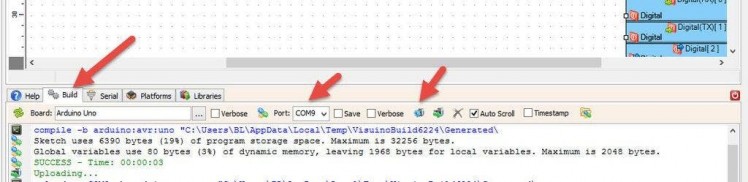
In Visuino, at the bottom click on the "Build" Tab, make sure the correct port is selected, then click on the "Compile/Build and Upload" button.
Step 8: Play
If you power the Arduino module the LED Display will Show 00:00, if you start pressing .a Button (Connected to pin 4) the time on the display will increase by 1second each time, once you set your time, press the other button to start the countdown. On the Countdown zero the Relay will turn the light bulb On.
Congratulations! You have completed your project with Visuino. Also attached is the Visuino project, that I created for this tutorial, you can download it and open it in Visuino: https://www.visuino.eu
Schematics, diagrams and documents
Code
Credits
Related products


Leave your feedback...