

Arduino Christmas Tree Lights

Made by Ron / Displays / Holidays / Home Automation / Kids & Family / Lights
About the project
Learn how to randomly change the LED color and ramp the brightness
Items used in this project
Hardware components

Story
Make a Christmass Tree Lights using Arduino. Lights will randomly change the color and change its brightness.
Watch the Video!
Project file can be downloaded below.
Step 1: What You Will Need
1 / 3

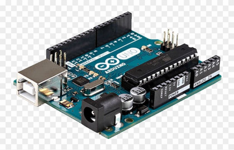
- Arduino UNO (or any other Arduino)
- 2X RGB LED or more
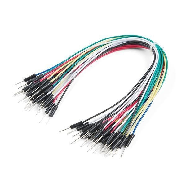
- Jumper wires
- Visuino program: Download Visuino
Step 2: The Circuit

- Connect RGB-LED1 pin [+] to Arduino pin [5V]
- Connect RGB-LED1 pin [R] to Arduino digital pin [3]
- Connect RGB-LED1 pin [G] to Arduino digital pin [5]
- Connect RGB-LED1 pin [B] to Arduino digital pin [6]
- Connect RGB-LED2 pin [+] to Arduino pin [5V]
- Connect RGB-LED2 pin [R] to Arduino digital pin [9]
- Connect RGB-LED2 pin [G] to Arduino digital pin [10]
- Connect RGB-LED2 pin [B] to Arduino digital pin [11]
Note: if you want to connect more LED, just connect them to the same pins
Step 3: Start Visuino, and Select the Arduino UNO Board Type
1 / 2

The Visuino: https://www.visuino.eu also needs to be installed. Download Free version or register for a Free Trial.
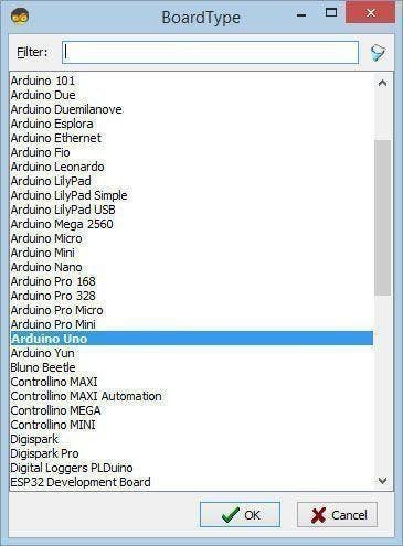
Start Visuino as shown in the first picture Click on the "Tools" button on the Arduino component (Picture 1) in Visuino When the dialog appears, select "Arduino UNO" as shown on Picture 2
Step 4: In Visuino Add, Set & Connect Components
1 / 8
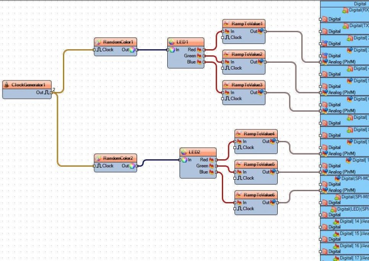
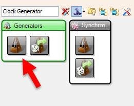


- Add "Clock Generator" component
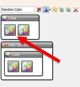
- Add 2X "Random Color" component
- Add 2X "RGB LED" component
- Add 6X "Ramp To Analog Value" component
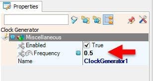
- Select "ClockGenerator1" and in the properties window set Frequency to 0.5
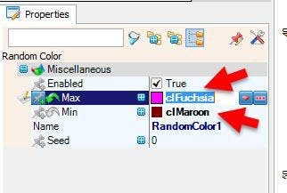
- Select "RandomColor1" and in the properties window set Max to clFuchsia and Min to clMaroon
- Select "RandomColor2" and in the properties window set Max to clWhite and Min to clMaroon
Note: You can choose diferent colors to test
- Connect "ClockGenerator1" pin [Out] to "RandomColor1" & "RandomColor2" pin [In]
- Connect "RandomColor1" pin [Out] to "LED1" pin [In]
- Connect "RandomColor2" pin [Out] to "LED2" pin [In]
- Connect "LED1" pin[R] to "RampToValue1" pin [In]
- Connect "LED1" pin[G] to "RampToValue2" pin [In]
- Connect "LED1" pin[B] to "RampToValue3" pin [In]
- Connect "LED2" pin[R] to "RampToValue4" pin [In]
- Connect "LED2" pin[G] to "RampToValue5" pin [In]
- Connect "LED2" pin[B] to "RampToValue6" pin [In]
- Connect "RampToValue1" pin [Out] to Arduino Analog PWM pin [3]
- Connect "RampToValue2" pin [Out] to Arduino Analog PWM pin [5]
- Connect "RampToValue3" pin [Out] to Arduino Analog PWM pin [6]
- Connect "RampToValue4" pin [Out] to Arduino Analog PWM pin [9]
- Connect "RampToValue5" pin [Out] to Arduino Analog PWM pin [10]
- Connect "RampToValue6" pin [Out] to Arduino Analog PWM pin [11]
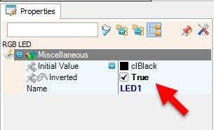
Note: If the LED1 is not shining then Select "LED1" and in the properties window set "Inverted" to True.
Note: If the LED2 is not shining then Select "LED2" and in the properties window set "Inverted" to True
Step 5: Generate, Compile, and Upload the Arduino Code

In Visuino, at the bottom click on the "Build" Tab, make sure the correct port is selected, then click on the "Compile/Build and Upload" button.
Step 6: Play
If you power the Arduino module the LEDs color will start to change on the LEDs.
Congratulations! You have completed your project with Visuino. Also attached is the Visuino project, that I created for this Tutorial, you can download it and open it in Visuino: https://www.visuino.eu
Schematics, diagrams and documents
Code
Credits
Related products


Leave your feedback...