
Arduino And Visuino: Directly Connected 2 X 16 Lcd Display

Made by Ron / Displays / Home Automation / Robotics / Sensors
About the project
Connect directly and program Character LCD display - quick and easy!
Project info
Difficulty: Easy
Platforms: Adafruit, Arduino, Visuino
Estimated time: 1 hour
License: GNU General Public License, version 3 or later (GPL3+)
Items used in this project
Hardware components

Story
Character LCD Displays are a very commonly used for Arduino projects, to display small amounts of textual information. The most common types are the basic directly connected displays, and the ones with I2C adapter.
In this Tutorial, I will show you how easy it is to connect LCD Display directly to Arduino Nano without the use of the I2C adapter, and program it with Visuino to display whatever is typed in a Serial Terminal.
Step 1: Components
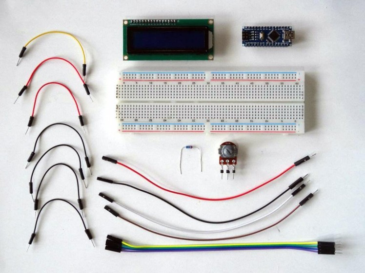
- One Arduino compatible board (I use Arduino Nano, because I have one, but any other will be just fine)
- One 16x2 LCD Display
- One 10K Potentiometer
- One 220 ohmResistor
- 8 Male-Female jumper wires
- 7 short Male-Male jumper wires
1 / 4 • Picture 1

Picture 1

Picture 2

Picture 3

Picture 4
- Place the LCD on the Breadboard
- Connect with jumper wire the "VSS" pin of the LCD to Ground of the power bus of the Breadboard (Black wire) (Picture 1)
- Connect with jumper wire the "VDD" pin of the LCD to Power of the power bus of the Breadboard (Red wire) (Picture 1)
- Connect the Male end of one of the Male-Female wires (White wire) to the "RS" pin of the LCD (Picture 2)
- Connect with jumper wire the "RW" pin of the LCD to Ground of the power bus of the Breadboard (Black wire) (Picture 3)
- Connect the Male end of one of the Male-Female (Brown wire) wires to the "E" pin of the LCD (Picture 4)
1 / 3 • Picture 1

Picture 1

Picture 2

Picture 3
- Connect the male ends of 4 Male-Female jumper wires to the D4 (Yellow wire), D5 (Green wire), D6 (Blue wire), and D7 (Purple wire) pins of the LCD (Picture 1)
- Connect the 220 ohm resistor between the "A" pin of the LCD and the Power of the power bus of the Breadboard (Picture 2)
- Connect with jumper wire the "K" pin of the LCD to Ground of the power bus of the Breadboard (Black wire) (Picture 3)
1 / 3 • Picture 1

Picture 1

Picture 2

Picture 3
- Place the Potentiometer on the Breadboard (Picture 1)
- Connect the middle (wiper) pin of the potentiometer to the "V0" pin of the LCD (Yellow wire) (Picture 2)
- Connect one of the end pins of the potentiometer to the Ground of the Power Bus of the Breadboard (Black wire) (Picture 3)
- Connect other end pin of the potentiometer to the Power of the Power Bus of the Breadboard (Red wire) (Picture 3)
1 / 2 • Picture 1

Picture 1

Picture 2
- Connect the Male end of a Male-Female jumper wire (Red wire) to the Power of the Power bus of the Breadboard (Picture 1)
- Connect the Male end of a Male-Female jumper wire (Black wire) to the Ground of the Power bus of the Breadboard (Picture 1)
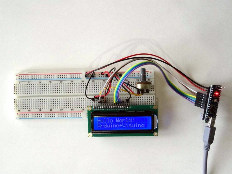
- Picture 2 shows the completely connected Breadboard
1 / 4 • Picture 1

Picture 1

Picture 2

Picture 3

Picture 4
- Connect the other end of the Ground wire (Black wire) to Ground pin of the Arduino board (Picture 1)
- Connect the other end of the Power wire (Red wire) to the 5V power pin of the Arduino board (Picture 1)
- Connect the other end of the "RS" wire (White wire) to the Digital 2 pin of the Arduino board (Picture 2)
- Connect the other end of the "E" wire (Brown wire) to the Digital 3 pin of the Arduino board (Picture 2)
- Connect the other end of the "D4" wire (Yellow wire) to the Digital 4 pin of the Arduino board (Picture 3)
- Connect the other end of the "D5" wire (Green wire) to the Digital 5 pin of the Arduino board (Picture 3)
- Connect the other end of the "D6" wire (Blue wire) to the Digital 6 pin of the Arduino board (Picture 3)
- Connect the other end of the "D7" wire (Purple wire) to the Digital 7 pin of the Arduino board (Picture 3)
- Picture 4 shows the all the Arduino and Breadboard connections
1 / 2 • Picture 1

Picture 1

Picture 2
To start programming the Arduino, you will need to have the Arduino IDE installed from here: http://www.arduino.cc/.
Please be aware that there are some critical bugs in Arduino IDE 1.6.6.
Make sure that you install 1.6.7 or higher, otherwise this Tutorial will not work!
The Visuino: https://www.visuino.com also needs to be installed.
- Start Visuino as shown in the first picture
- Click on the "Tools" button on the Arduino component (Picture 1) in Visuino
- When the dialog appears, select Arduino Nano as shown in Picture 2
1 / 5 • Picture 1

Picture 1

Picture 2

Picture 3

Picture 4

Picture 5
- Type "lcd" in the Filter box of the Component Toolbox then select the "Liquid Crystal Display (LCD)" component (Picture 1), and drop it in the design area
- Connect the "RegisterSelect" output pin of the LiquidCrystalDisplay1 component to the "Digital" input pin of the "Digital[ 2 ]" channel of the Arduino component (Picture 2)
- Connect the "Enable" output pin of the LiquidCrystalDisplay1 component to the "Digital" input pin of the "Digital[ 3 ]" channel of the Arduino component (Picture 3)
- Connect the "Data0" output pin of the LiquidCrystalDisplay1 component to the "Digital" input pin of the "Digital[ 4 ]" channel of the Arduino component (Picture 4)
- Connect the "Data1" output pin of the LiquidCrystalDisplay1 component to the "Digital" input pin of the "Digital[ 5 ]" channel of the Arduino component (Picture 4)
- Connect the "Data2" output pin of the LiquidCrystalDisplay1 component to the "Digital" input pin of the "Digital[ 6 ]" channel of the Arduino component (Picture 4)
- Connect the "Data3" output pin of the LiquidCrystalDisplay1 component to the "Digital" input pin of the "Digital[ 7 ]" channel of the Arduino component (Picture 4)
- Connect the "Out" pin of the "Serial[ 0 ]" channel of the Arduino component to the "In" pin of the LiquidCrystalDisplay1 component (Picture 5)
1 / 2 • Picture 1

Picture 1

Picture 2
- In Visuino, Press F9 or click on the button shown on Picture 1 to generate the Arduino code, and open the Arduino IDE
- In the Arduino IDE, click on the Upload button, to compile and upload the code (Picture 2)
1 / 3 • Picture 1

Picture 1

Picture 2

Picture 3
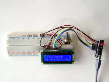
Congratulations! You have completed the project.
Picture 1 shows the connected and powered up project.
If you open Serial Terminal in the Arduino IDE or Visuino, type some text and press Enter, you should see the text appearing on the LCD.
Avoid entering lines of text of more characters than the LCD has per line, as you can overflow its buffers.
You may need to adjust the potentiometer to get clearly displayed text.
On Picture 3 you can see the complete Visuino diagram.
Also attached is the Visuino project, that I created for this Tutorial. You can download and open it in Visuino: https://www.visuino.com
Schematics, diagrams and documents
Credits
Related products


Leave your feedback...