
Arduino And Visuino: Control Servos With A Joystick

Made by Ron / Home Automation / Robotics / Sensors
About the project
Controlling Servos connected to Arduino with Joystick is very common task. With Visuino, achieving this has never been easier!
Project info
Difficulty: Easy
Estimated time: 1 hour
License: GNU General Public License, version 3 or later (GPL3+)
Items used in this project
Hardware components

Software apps and online services
Story
Controlling Servos connected to Arduino with Joystick is very common task. With the help of Visuino, an easy to use graphical development environment for Arduino, achieving this has never been easier!
Components
1 / 2 • Picture 1

Picture 1

Picture 2
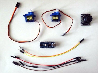
- One Arduino compatible board (I use Arduino Nano, because I have one, but any other will be just fine)
- One Joystick that I got from this cheap 37 sensors set.
- 2 Small Servos
- 2 Male-Female jumper wires
- 5 Female-Female jumper wires
- One K2 Breadboard power supply with adapter
1 / 3 • Picture 1

Picture 1

Picture 2

Picture 3
- Connect the Male end of the Male-Female jumper wires to the Control wires of the Servos as shown on Picture 1
- Connect the Servo connectors to the K2 Power Supply in such a way that the Ground of the Power Supply is connected to the Groundwire of the Servo, and the Power of the Power Supply to the Powerwire of the Servo as shown on Picture 2, and 3
- Make sure the power supply is set to 5V
1 / 4 • Picture 1

Picture 1

Picture 2

Picture 3

Picture 4
- Connect a Female-Female wire (Black wire) to the Ground of the Power Supply as shown on Pictures 1 and 2
- Connect the other end of the Ground wire (Black wire) to the Ground pin of the Arduino (Picture 3)
- Connect the Signal wire (Yellow wire) from one of the Servos to Digital pin 2 of the Arduino (Picture 3)
- Connect the Signal wire (Orange wire) from the other Servo to Digital pin 3 of the Arduino (Picture 3)
- Picture 4 shows the Arduino Nano pins that ware connected in this step
1 / 3 • Picture 1

Picture 1

Picture 2

Picture 3
- Connect Female-Female wires to the Ground (Black wire), Power (Red wire), VRx (White wire), and VRy (Brown wire) of the Joystick as shown in Picture 1
- Connect the Ground wire (Black wire) to the Ground pin of the Arduino board (Picture 2)
- Connect the Power wire (Red wire) to the 5V Power pin of the Arduino board (Picture 2)
- Connect the VRx wire (White wire) the the Analog 1 pin of the Arduino board (Picture 2)
- Connect the VRy wire (Brown wire) the the Analog 0 pin of the Arduino board (Picture 2)
- Picture 3 shows the Arduino Nano pins that ware connected in this step
1 / 2 • Picture 1

Picture 1

Picture 2
To start programming the Arduino, you will need to have the Arduino IDE installed from here: http://www.arduino.cc/ .
Please be aware that there are some critical bugs in Arduino IDE 1.6.6. Make sure that you install 1.6.7 orhigher, otherwise this Tutorial will not work!
The Visuino: https://www.visuino.com also needs to be installed.
- Start Visuino as shown in the first picture
- Click on the "Tools" button on the Arduino component (Picture 1) in Visuino
- When the dialog appears, select Arduino Nano as shown in Picture 2
1 / 3 • Picture 1

Picture 1

Picture 2

Picture 3
- Type "ser" in the Filter box of the Component Toolbox then select the "Servo" component (Picture 1), and drop two of them in the design area
- Connect the "Out" pin of the Servo1 component to the "Digital" input pin of "Digital[ 2 ]" channel of the Arduino component (Picture 2)
- Connect the "Out" pin of the Servo2 component to the "Digital" input pin of "Digital[ 3 ]" channel of the Arduino component (Picture 3)
1 / 4 • Picture 1

Picture 1

Picture 2

Picture 3
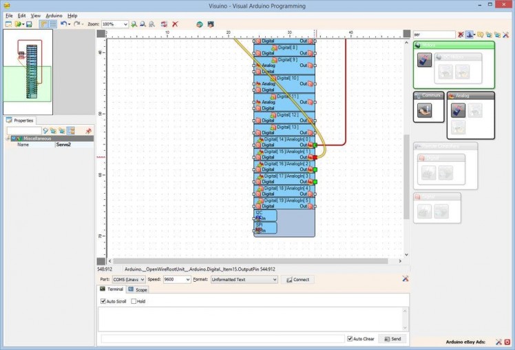
- Connect the "In" pin of the Servo1 component (Picture 1) to the "Out" pin of "Digital[ 14 ]/AnalogIn[ 0 ]" channel of the Arduino component (Picture 2)
- Connect the "In" pin of the Servo2 component (Picture 3) to the "Out" pin of "Digital[ 15 ]/AnalogIn[ 1 ]" channel of the Arduino component (Picture 4)
1 / 2 • Picture 1

Picture 1

Picture 2
- In Visuino, Press F9 or click on the button shown on Picture 1 to generate the Arduino code, and open the Arduino IDE
- In the Arduino IDE, click on the Upload button, to compile and upload the code (Picture 2)
1 / 2 • Picture 1

Picture 1

Picture 2
Picture 1 shows the connected and powered up project.
If you move the Joystick Left-Right, and Up-Down the Servos will follow the movements.
Congratulations! You are now in control of your Servos!
On Picture 2 you can see the complete Visuino diagram.
Also attached is the Visuino project, that I created for this Tutorial. You can download and open it in Visuino: https://www.visuino.com
Credits
Related products


Leave your feedback...