
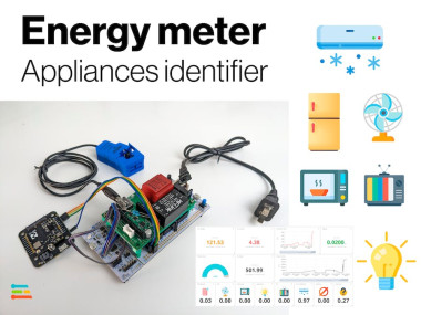
Appliances Identifier Smart Energy Meter

Made by mcmchris / Artificial intelligence / Environmental Sensing / Home Automation / Sensors / IoT
About the project
It measures Voltage, Current, Power, Power Factor and Energy, and at the same time, tells you which appliance is connected, cloud monitored.
Project info
Difficulty: Difficult
Platforms: Ubidots, Arm, Edge Impulse, JLCPCB, Blues Wireless
Estimated time: 2 days
License: GNU General Public License, version 3 or later (GPL3+)
Items used in this project
Hardware components

Software apps and online services
Story
Electrical energy is crucial in our lives, and it is very important to know how we use it in order to be aware of how to do it prudently.
To create a real energy meter we must measure at least AC voltage and current, but... As we are working with alternating current, active/real power isn't just V*I, it must contain a power factor scaler, so the actual formula is:
P=V*I*cos(φ)
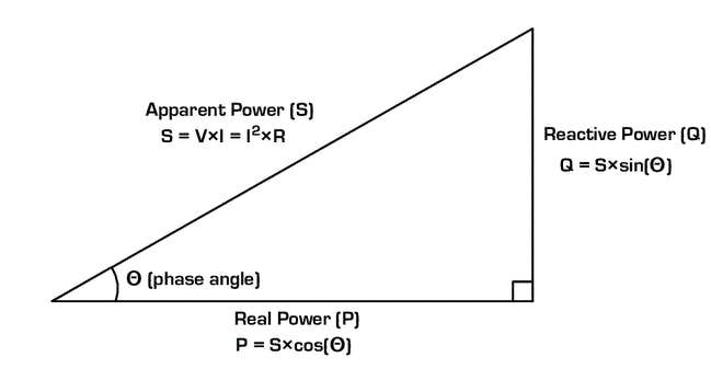
Figure 1 - power triangle
Where cos(φ) stands for the power factor that correlates with the offset between the voltage and current signals:
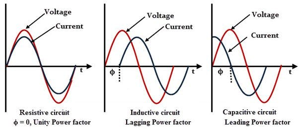
Figure 2 - power factor behavior
Considering this, now it's clear why just having a voltage and a current value is not enough, we need something that lets us measure the power factor to calculate the real power we are using, for that it's important to have analog current and voltage sensors that let our microcontroller to analyze the raw waveforms of each one.
About identifying appliancesIn our home's power grid there are a lot of different appliances, that uses the energy their own way, there could be from resistive loads (heaters, irons, toasters) to inductive loads (fans, refrigerator, microwaves), as we can see on "figure 2", the nature of the loads affects the power factor, but not just that, it can influence how the current waveform looks giving space to harmonics to appear.
I won't get too deep on this, but technically, the harmonics of a current waveform are sinusoidal waves whose frequency is an integer multiple of the fundamental frequency.
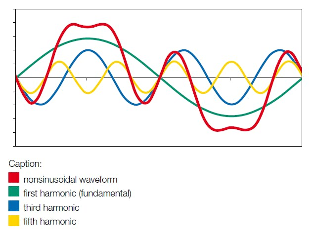
Figure 3 - Harmonics on a current waveform
Thanks to Machine Learning algorithms we can analyze the current waveform of a specific appliance and extract its characteristics harmonics alongside its power variables to learn about them and then use this data for further identification.
The Hardware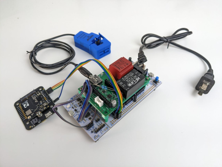
Figure 4 - Project hardware
- MCU: STM32F767ZI
- Wireless communication: Blues Wireless WiFi Notecard + Notecarrier-B
- Current sensor: 0-100A SCT013 (100A:50mA)
- Sensors front end: Custom PCB (see schematic section)
Pin configuration:
- STM32 pins --------- Other hardware
- PF_7 (TX) ------------- Notecard RX pin
- PF_6 (RX) ------------- Notecard TX pin
- A1 (PC_0) -------------- corCT (CT sensor input from PCB)
- A2 (PA_3) -------------- volt (PT sensor input from PCB)
- PB_9 -------------------- I2C SDA (digital potentiometer)
- PB_8 -------------------- I2C SCL (digital potentiometer)
You can support me in buying the PCB manufacturing file (Gerber, BOM and Pick&Place). Use this coupon code: 50OFFPCB for a 50% discount.
Note: I ordered my PCBs at JLCPCB PCBA assembly services.
How does it work?- Current front end:
The CT sensor output is level shifted and amplified by an instrumentation opamp with a digital gain adjustment between W1 and A1.

Figure 5 - Current front end schematic
In the "corCT" output appears the analog current waveform from the load ready to be sampled by the MCU ADC.
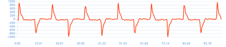
Figure 6 - LED light bulb current waveform
- Voltage front end:
The PT sensor output is level shifted and coupled by a voltage follower to avoid MCU ADC impedance.
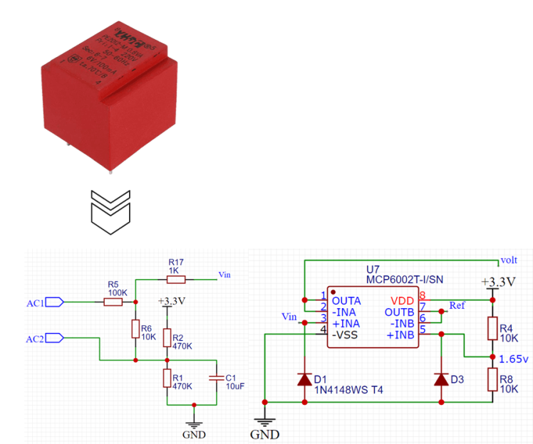
Figure 7 - Voltage front end schematic
In the "volt" output appears the analog voltage waveform from the grid ready to be sampled by the MCU ADC.
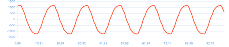
Figure 8 - Voltage waveform
Explaining the process:
The voltage and current signals are processed by the MCU, and from them, it extracts the electrical variables of:
- RMS voltage (V).
- RMS current (A).
- Power (W).
- Power factor.
- Energy (kWh).
The raw voltage and current waveforms also go to a machine learning block that analyzes the current harmonics and compares the results with previously trained information to identify which load/appliance is connected at this moment.
The inference output and electrical variables are all sent through the WiFi notecard to Ubidots for visualization.
Training the ModelI made a trainer version of my code, that uses the Edge Impulse Ingestion service to send periodically over HTTP posts the samples, so I can let the appliances work for hours on it normal basis.
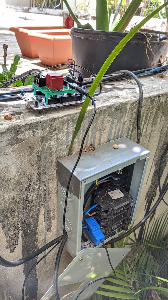
Figure 9 - Sampling AC for training

Figure 10 - Sampling Refrigerator for training
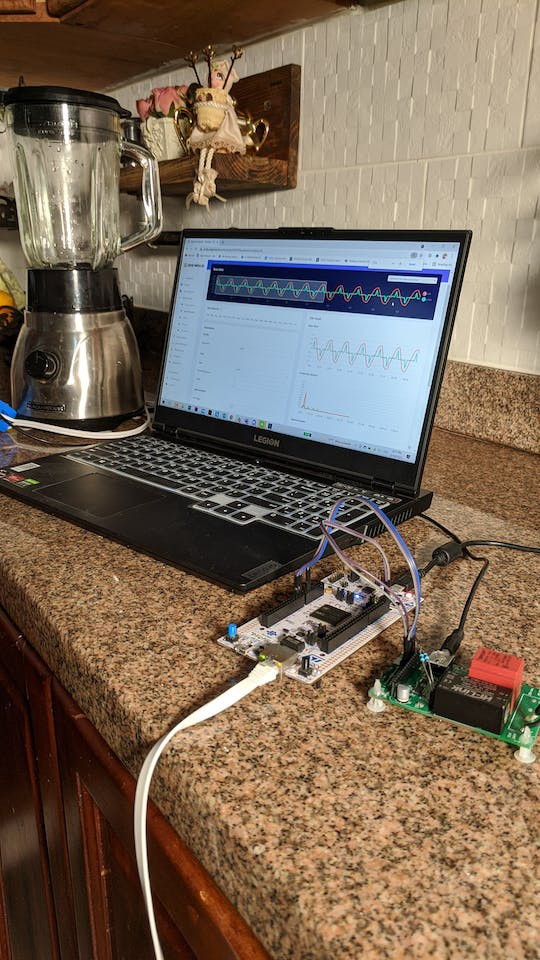
Figure 11 - Sampling blender for training (not used at the end)
I trained the model to be able to identify these appliances:
- Refrigerator (inverter and non-inverter).
- Fan (ceiling and floor).
- Light bulb (Incandescent and LED).
- Microwave.
- Air conditioner (inverter).
- TV (smart LCD).
The input variables to build the model were:
- Voltage waveform.
- Current waveform.
- RMS current (value).
- Active power (value).
- Power factor (value).
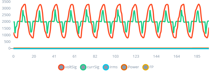
Figure 11.1 - Multiple variables input
Current vs Voltage waveforms of each appliance:
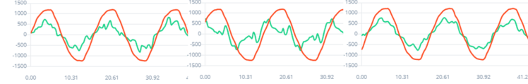
Figure 12 - Air conditioner
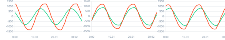
Figure 13 - Fan at different speeds
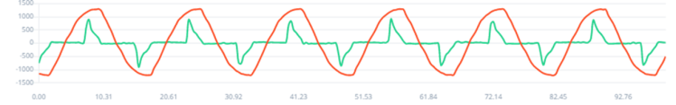
Figure 14 - TV
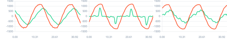
Figure 15 - Inverter Refrigerator
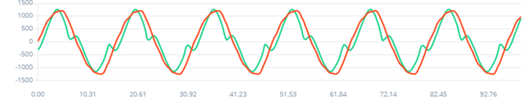
Figure 16 - Microwave
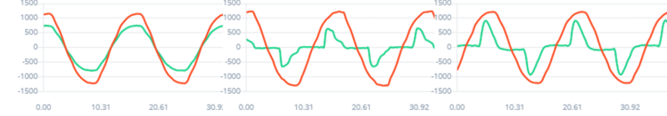
Figure 17 - Light bulbs (LED, filament)
Impulse design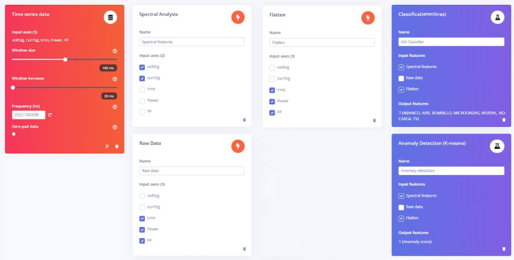
Figure 18 - time series, processing and learning blocks.
Spectral features:
- To analyze voltage and current signals in the frequency domain.
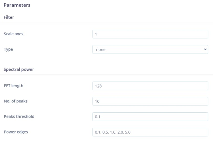
Figure 19 - Spectral features settings
Flatten:
- To extract the average of RMS current, Power and Power factor.
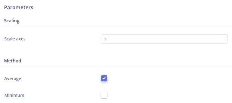
Figure 20 - Flatten settings (just average)
Raw data:
- To extract patterns from RMS current, Power and Power factor.
NN Classifier:
- To learn from features created from the blocks mentioned before.
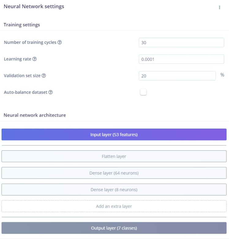
Figure 21 - NN settings and architecture
Anomaly detection:
- To identify a new load non trained.
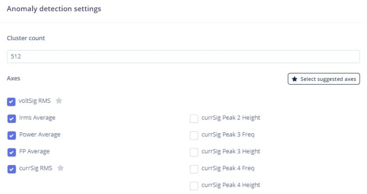
Figure 22 - Anomaly detection settings
Model performance results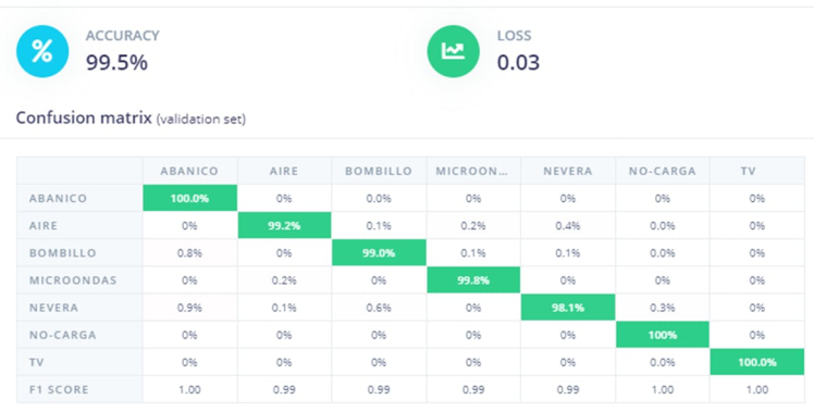
Figure 23 - Model confusion matrix
I achieved very good accuracy in differentiating the appliances.
Note: Here is the published project that you can clone and modify on Edge Impulse
Deploy the model back to the microcontrollerI followed this guide from Edge Impulse to clone an example code for the Mbed CLI framework and start coding on top of it.
Steps to deploy the model:
- Export a C++ library of the model.
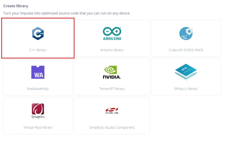
Figure 24 - Library export
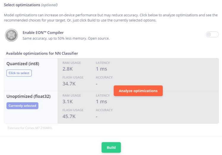
Figure 25 - Optimizations settings
Download the .zip and make sure you can find it, we will use it later.
file and place the contents in the 'example-standalone-inferencing-mbed' folder (which you downloaded above). Your final folder structure should look like this:
example-standalone-inferencing-mbed
|_ Makefile
|_ README.md
|_ build.sh
|_ edge-impulse-sdk
|_ model-parameters
|_ source
|_ tflite-model- Create an account for free on notehub.io.
- Login and click on Create Project name your project and define a ProductUID.
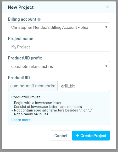
Figure 26 - Notehub project creation
- Create an Ubidots account and create a new device.

Figure 28 - Ubidots sign up
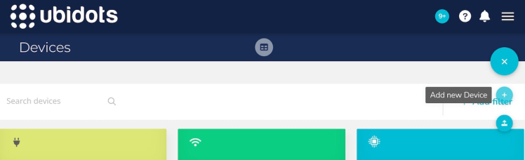
Figure 29 - Add a new blank device
- Copy your account default token by navigating to your API credentials.
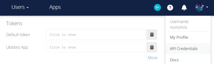
Figure 30 - Copy your default token
- Back to Notehub, select your project and navigate to Routes and click on New Route.
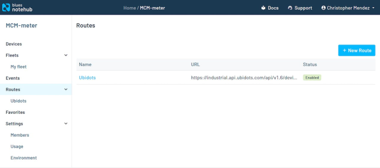
Figure 31 - Route creation
- Select the General HTTP/HTTPS Request/Response route type.

Figure 32 - Route type
- Give the route a name, and for the URL, enter
https://industrial.api.ubidots.com/api/v1.6/devices/[device-name]/, substituting in the device name you created earlier (without brackets) — in this case:
https://industrial.api.ubidots.com/api/v1.6/devices/ai-energy-meter/
- Add a header name of
X-Auth-Tokenwith a value of the default token you copied earlier.
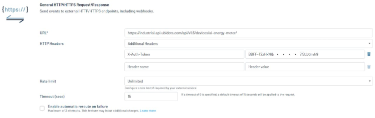
Figure 33 - Adding the credentials
In the Notefiles dropdown, choose Select Notefiles and specify data.qo. Then, in the Transform JSON option, select JSONata Expression and enter the following expression.
{
"voltage": {"value": body.voltage, "timestamp": when * 1000},
"current": {"value": body.current, "timestamp": when * 1000},
"energy": {"value": body.energy, "timestamp": when * 1000},
"power": {"value": body.power, "timestamp": when * 1000},
"pf": {"value": body.pf, "timestamp": when * 1000},
"ac": {"value": body.ac, "timestamp": when * 1000},
"fan": {"value": body.fan, "timestamp": when * 1000},
"lightbulb": {"value": body.lightbulb, "timestamp": when * 1000},
"microwave": {"value": body.microwave, "timestamp": when * 1000},
"nothing": {"value": body.nothing, "timestamp": when * 1000},
"refri": {"value": body.refri, "timestamp": when * 1000},
"tv": {"value": body.tv, "timestamp": when * 1000},
"unknown": {"value": body.unknown, "timestamp": when * 1000}
}- Click Save and we should be ready to start receiving data and sending it to Ubidots.
- Clone the code from my repository.
- Open it with your favorite code editor (I use Visual Studio).
- The only thing you need to modify from the code to bind it with your Notehub account is the ProductUID on line 23.
#define PRODUCT_UID "......" // Notehub device identifier- That's it, let's compile the code and flash the board.
- For this, we are using the Mbed CLI. Just open the (CMD) terminal on the directory of the code folder and type.
mbed compile -t GCC_ARM -m auto -f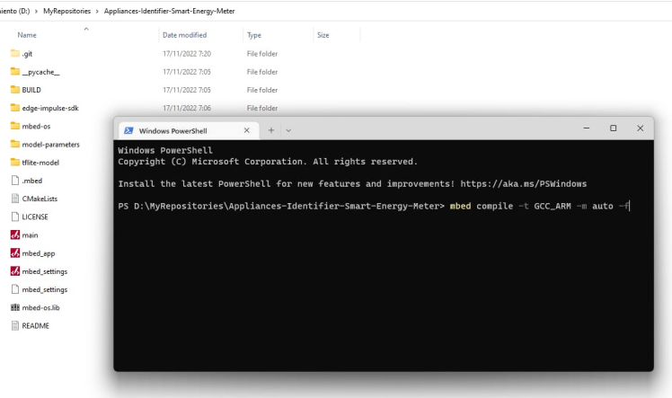
Figure 34 - Compile and flash the code.
Important: the compilation was tested with the 6.3.1 compiler version, may fail with new versions.
Wait for the MCU to be flashed and that's it.
- Connects the WiFi Notecard to your WiFi by pressing the button on the Notecard and searching a WiFi AP in your smartphone called "Notecard" click on it to connect and a web portal will appear where you can enter your WiFi credentials.
1 / 2 • Figure 35 - WiFi setup
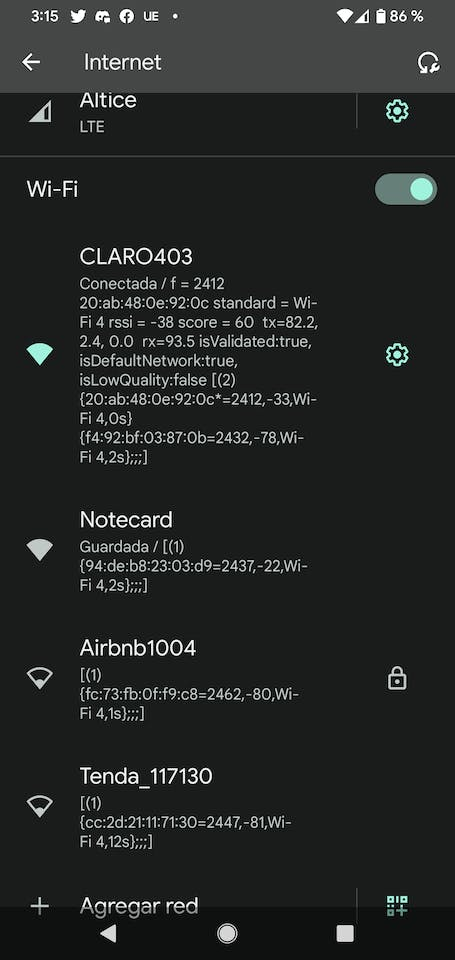
Figure 35 - WiFi setup
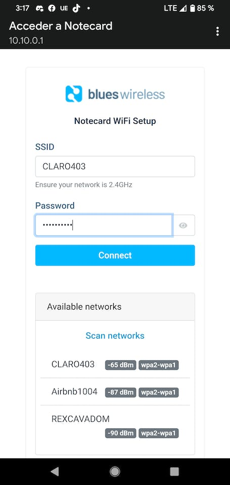
Figure 36 - Enter WiFi credentials
Once connected, it should start sending the inference data and energy variables to Ubidots every 10 seconds.
Testing and demos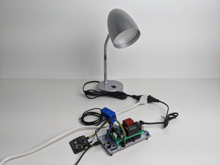
Figure 37 - Load off

Figure 38 - Ubidots shows that Nothing is powered on
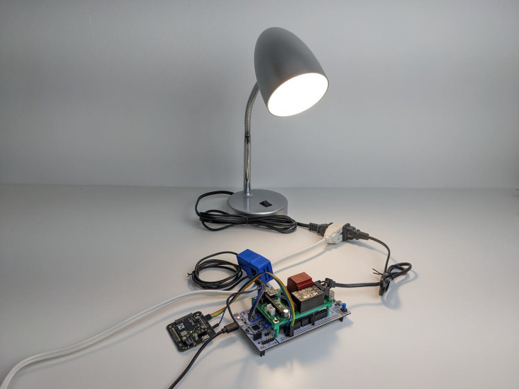
Figure 39 - Light is on
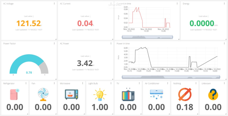
Figure 40 - Light bulb is infered and show power measurements
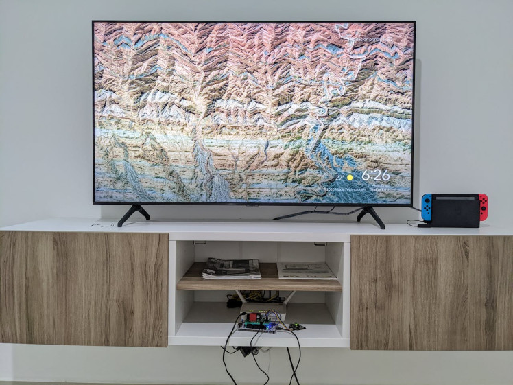
Figure 41 - TV is connected
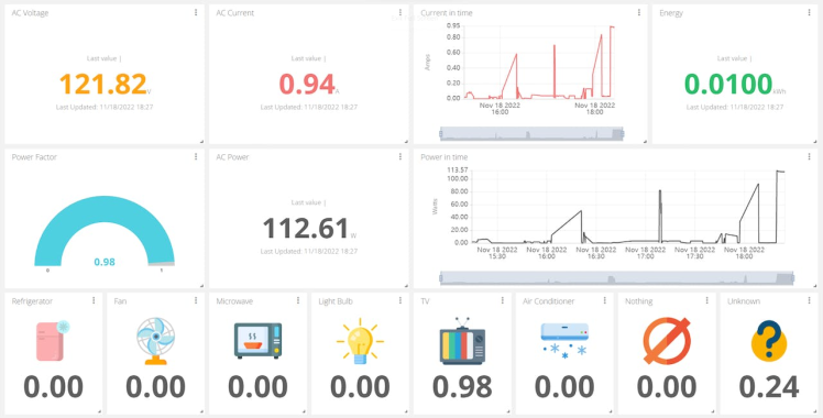
Figure 42 - TV infered and power measurements
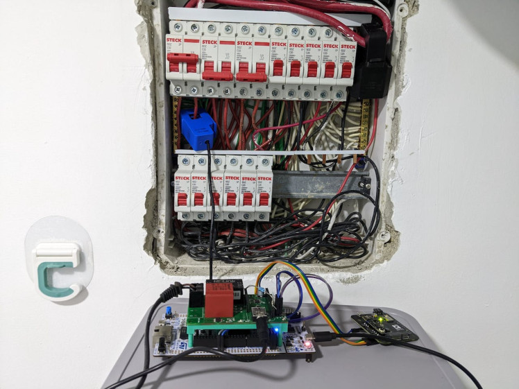
Figure 43 - Air conditioner turned on , CT on breaker
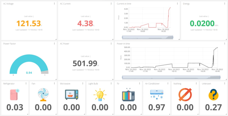
Figure 44 - AC infered and power measurements
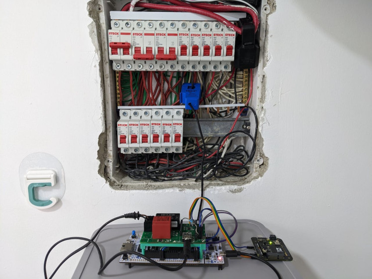
Figure 45 - Connected on Refrigerator breaker
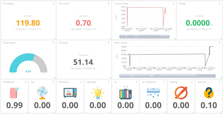
Figure 46 - Refrigerator infered and power measurements
Note: I wasn't able to show you the project with a microwave (I moved from home I don't have one now) but I promise it works!
Conclusions and future workThis project thought me a lot of things, it was able to show me (In a tangible way) the relationship between efficiency and the power factor of an appliance. Also the hidden information behind the harmonics of a load.
One of my favorite achievements was the accuracy of Energy (kWh) metering and seeing the autogain system amplifying the waveform of low-current consumption appliances.
The project can be improved in different ways I can list here:
- Training the model with more than 5 different (brands, power, and type) of appliances.
- Modifying the model so it can identify several appliances connected at once.
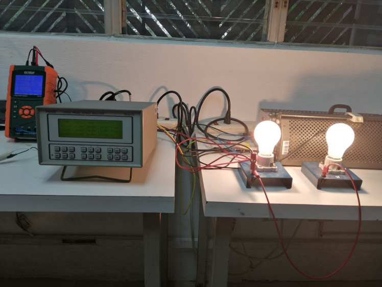
Figure 47 - Power measurement calibration process using two professional meters
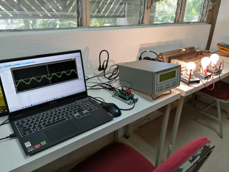
Figure 48 - Testing autogain adjustment and power factor
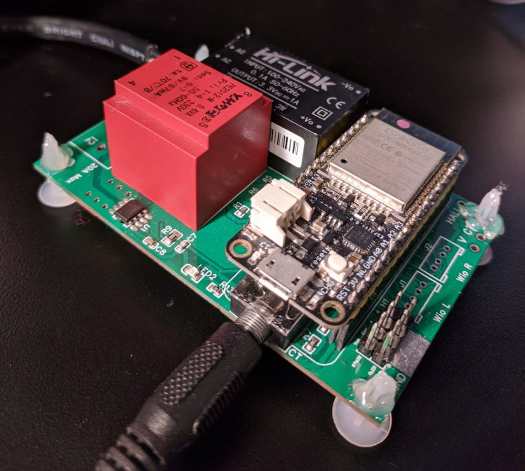
Figure 49 - The project was first design considering the ESP32 as the main CPU (didn't work)
Schematics, diagrams and documents
Code
Credits
Leave your feedback...