
Self-activating Box Machine Using Qr Code

Made by AntonioDG030 / 3D Printing / Artificial intelligence / Robotics / Sensors / IoT
About the project
In this project, discover how to build an automatic sliding door that can be opened through a QR code. The project is powered by Arduino software, MIT App Inventor, and a few Arduino hardware components.
Project info
Difficulty: Moderate
Platforms: Android, Arduino, Android Things, Mac, MIT App Inventor
Estimated time: 2 hours
License: GNU General Public License, version 3 or later (GPL3+)
Items used in this project
Hardware components


Hand tools and fabrication machines

Story
As aforementioned, the project is mainly about building an automatic sliding door that can be opened/accessed through a QR code. The project is powered through Arduino software, MIT App Inventor, and a few Arduino hardware components.
I decided to create the project as I wanted to expand my knowledge mainly about programming. I am still a young student who aspires to be a Mechanical Engineer as my profession someday.
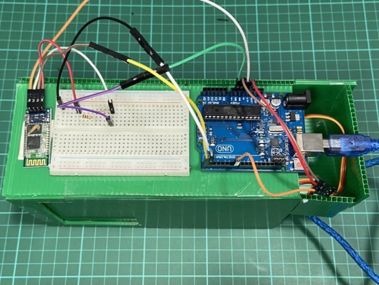
Anyway, so how does it work? First, we basically have to connect everything through jumper wires. The circuit diagram will serve as a guide in creating the project. Attached below is the sample circuit I did (check the attachments part for a more detailed diagram).
What does each component do?
Arduino Uno - This is where your programs from your computer will go in order for everything to work. The board is equipped with digital and analog I/O pins that may be interfaced to other circuits.
Breadboard - They enable us to easily connect components or wires.
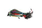
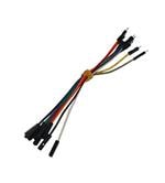
Jumper Wires - They are used to connect two points in a circuit.
1k Ohm Resistors - They are used to reduce current flow and adjust signal levels.
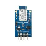
HC05 Bluetooth Module - A simple Bluetooth SPP (Serial Port Protocol) module designed for setting up a wireless serial connection.
SG90 Servo Motor - A light weight server motor that rotates up to 180 degrees (the servo motor will be the one responsible for the door's movement.)
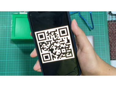
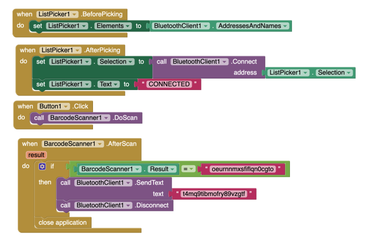
Then, once the circuit and everything are attached, now is the time for the programming part. We first have to create an app through MIT App Inventor that will allow the android mobile phone's camera to read the qr code.
The very first part of the program allows you to select your bluetooth module so you could connect it with your arduino. The second part says that once the bluetooth is paired, it will display a message that says "Connected".
After, I generated 2 random strings using goqr.me (one for the qr code’s result and one for the bluetooth client to send to arduino.) So, once the qr code is scanned, it will now show us the result - 1st string. Once the app reads the 1st string, it will now call the bluetooth client. Consequently, the client will now send the 2nd string to arduino through the bluetooth module, and if that string matches with the ones we wrote in arduino, the action would be “door open”. After that, the application closes, resetting everything.
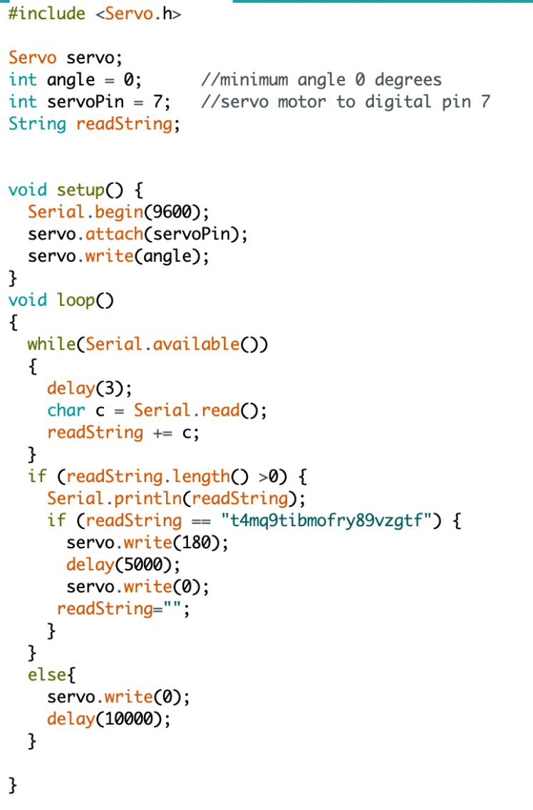
Moving on to the Arduino part, the image below shows the program. The first part tells the Arduino editor that you want access to the Servo library functions with this declaration at the start of your sketch, before the setup function. The very second part (Servo servo;) is used to declare and name an instance of the Servo library for each signal you want to send, between the #include and the setup function. The int angle = 0 assigns the minimum angle to 0 degrees, while the int servoPin assigns the servo motor to digital pin 7. String readString is used to store the text.
Serial.begin(9600) tells the Arduino to get ready to exchange messages with the Serial Monitor at a data rate of 9600 bits per second. servo.attach(servoPin) sets the servo to digital pin 7 while servo.write(angle) sets the starting angle to "angle" which we have declared a while ago as 0.
Inside the void loop:
- Until the expression inside in the parenthesis () is false, a while loop will continue constantly and endlessly.
- The serial port's read-only stored bytes are obtained by Arduino's serial.available() function from there.
- There will be a delay of 3 milliseconds after.
- char is a data type used to store a character value. The char c is stored in the Serial.read(); function.
- readString += c is used to increment the value of readString by c.
- The length function returns the length of the String, in characters.
- If there are more than 0 characters, it will display the value of readString. If the readString matches with the second string which was sent by the Bluetooth client earlier, the servo motor rotates 180 degrees at a delay of 5 seconds. The else statement closes the door at a delay of 10 seconds.
You may watch the video below in order for you to clearly see and check how it's working. Note: This is just a prototype. You may use 3D printed materials, etc.
Schematics, diagrams and documents
Code
Credits
Related products


Leave your feedback...