
Am/fm/sw Radio Receiver - Si4730 / Si4735

Made by CesarSound / Astronomy / Communication / Displays / Music / Retro Tech
About the project
DIY AM/FM/SW/ DSP radio receiver, using Arduino Uno/Nano and a color display TFT ST7735 1.8in.
Project info
Difficulty: Moderate
Platforms: Arduino, Atmel, Silicon Labs, EduBlocks
Estimated time: 2 hours
License: GNU General Public License, version 3 or later (GPL3+)
Items used in this project
Hardware components


View all
Story
- This is my design of an AM/FM/SW radio receiver with DSP technology.
Features:
This Arduino radio receiver has an attractive look and nice features using an inexpensive color TFT / Arduino and few componets and delivery surprisingly good performance.
It includes the indication of the frequency in large numbers in the style of vintage seven segments, two bargraphs for indicating the signal strength, selection of 7 BW filters for AM and 5 BW filters for FM, indication of the wavelength of the band, change of tune step, Stereo/Mono indication, 14 bands for coverage of LW / MW / SW / CB ranging from 150kHz-30MHz / commercial FM band 64-108MHz and 2 color scheme for the display.
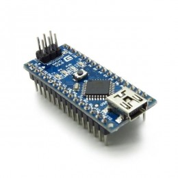
I used the Arduino Nano (the Pro Mini or Uno will also work) to control the Si4730-D60 integrated circuit (see notes below). The Si4730 is a complete receiver with DSP (digital signal processing) technology, similar to that used in SDR receivers.
The Arduino sends the control commands to the Si4730-D60 via the I2C data interface. The graphical interface is made up of a 1.8in ST7735 color TFT display, via SPI data interface.
An external audio amplifier must be used to amplify the sound of this radio. One suggestion is to use the amplified speakers used on computers or any other amplifier that has a line input.
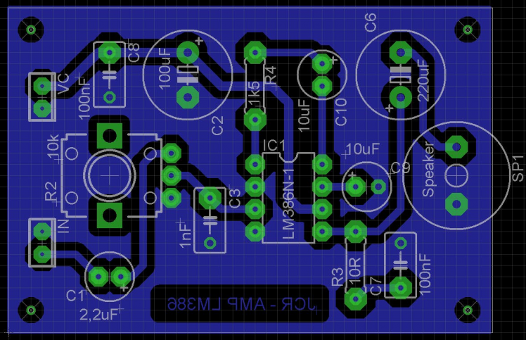
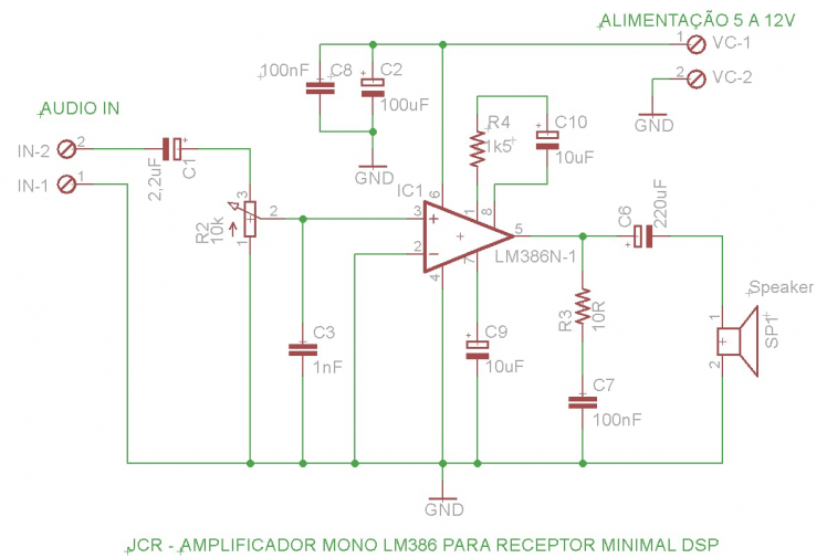
Another option is to assemble a simple DIY audio amplifier with the LM386 IC. See below a complete project of the audio amplifier that I assembled at home using the LM386. If you want a stereo amplifier, assemble 2 of these.
I wrote this code (sketch) in a simple way, allowing beginners (and advanced) to make their own modifications and customize the radio according to their needs.
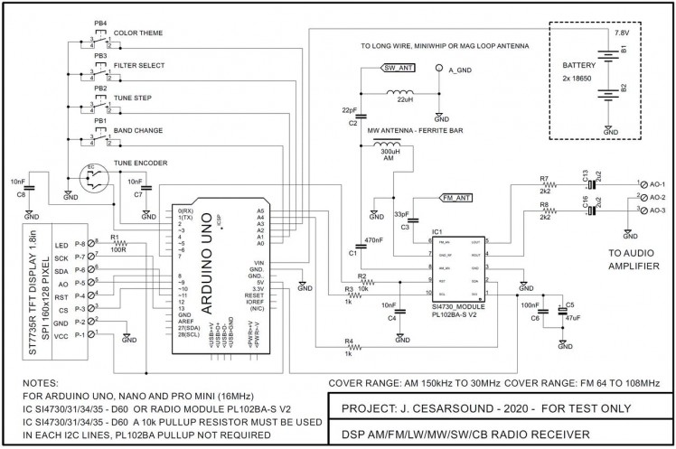
As can be seen in the wiring diagram, it is not necessary to use bi-directional Logic Level Converter, making the circuit even simpler and the circuit will works perfectly without it.
Note that the antenna input circuit (RF front end) is very simple, I did not use an RF pre-amp (LNA) or even more elaborate LPF / BPF filters and even so the results were great and surprised me. Watch the videos demonstrating the operation below.
Wiring diagram (schematics):
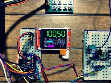
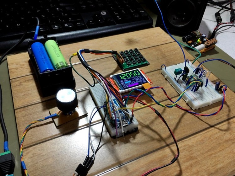
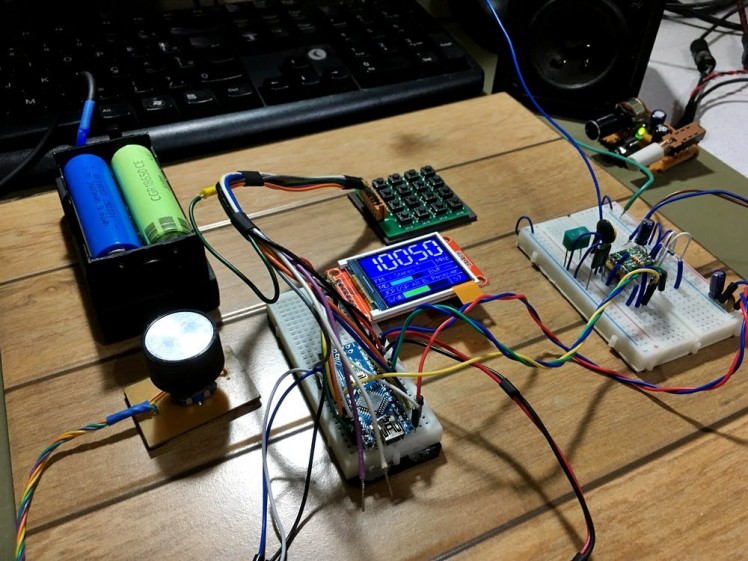
Here are some pictures of the circuit I set up:
1 / 2
Radio operation:
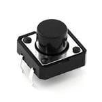
The radio is operated using a rotary encoder and 4 buttons, as described below:
Rotary encoder: Tune radio stations.
-
Button 1: Change bands (14 AM and 1 FM).
-
Button 2: Change tuning steps for AM (1 kHz, 5 kHz, 10 kHz).
-
Button 2: Change tuning steps for FM (100 kHz, 200 kHz). NEW
-
Button 3: Select AM bandwidth filters (6, 4, 3, 2.5, 2, 1.8, 1 kHz).
-
Button 3: Select FM bandwidth filters (Auto, 110, 84, 60, 40 kHz). NEW
Button 4: Select display colour scheme (2 options).
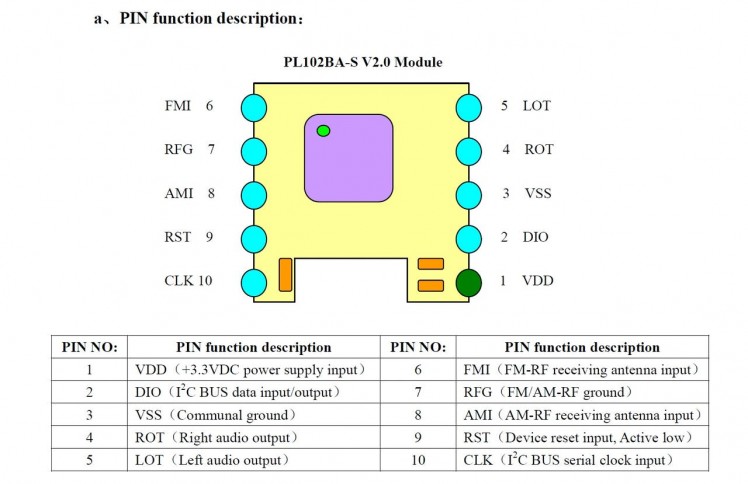
Notes on the PL102BA-S V2 and theDSPradio chip (IC):
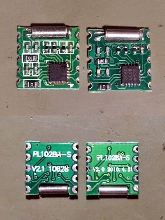
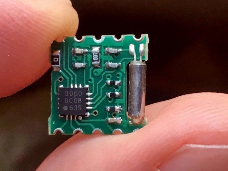
The radio module used here is the PL102BA-S V2 (Si4730-D60 IC). Only the version with the Si4730-D60 IC marked 3060 will work in the shortwave range. Be aware that modules marked NE928-10A V.01 only support AM/FM (not SW), as they use the Si4730-D20 (marked 3020).
2-Below are some picures and the pinout of a PL102BA-S V2:
1 / 4
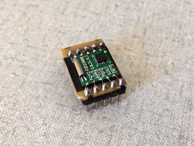
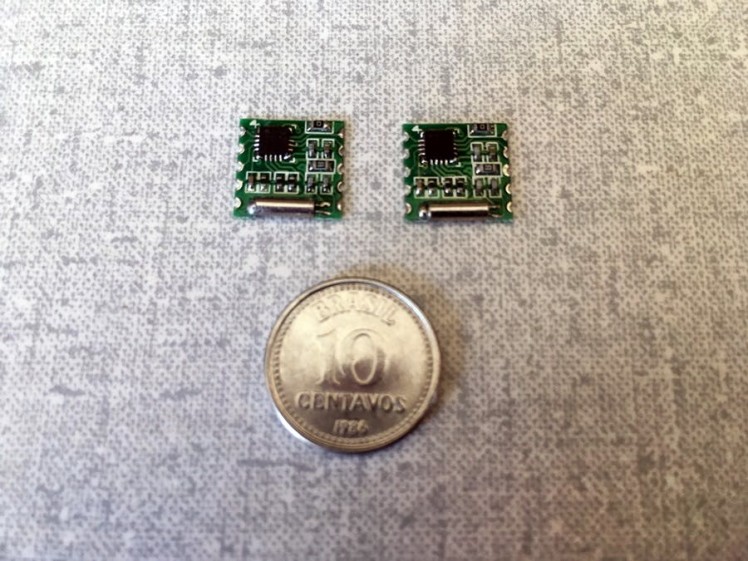
3-The PL102BA-S V2 module can be purchased in Aliexpress.
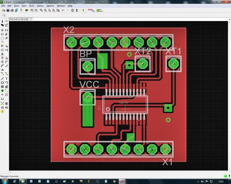
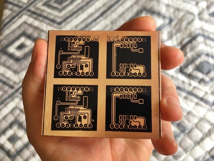
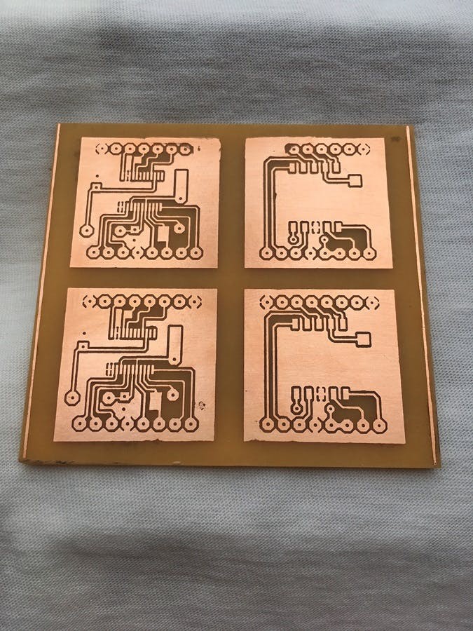
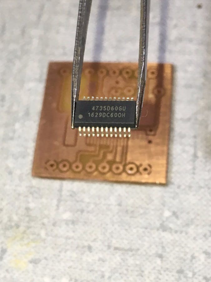
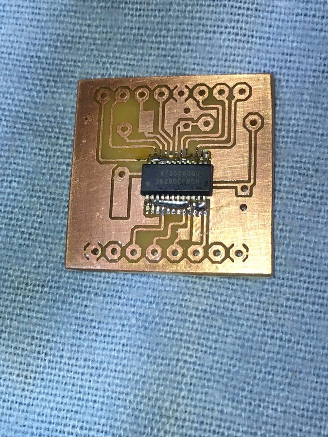
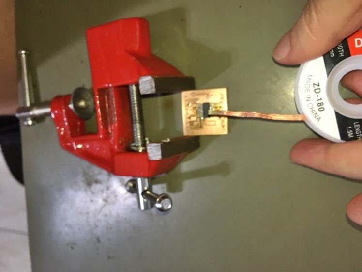
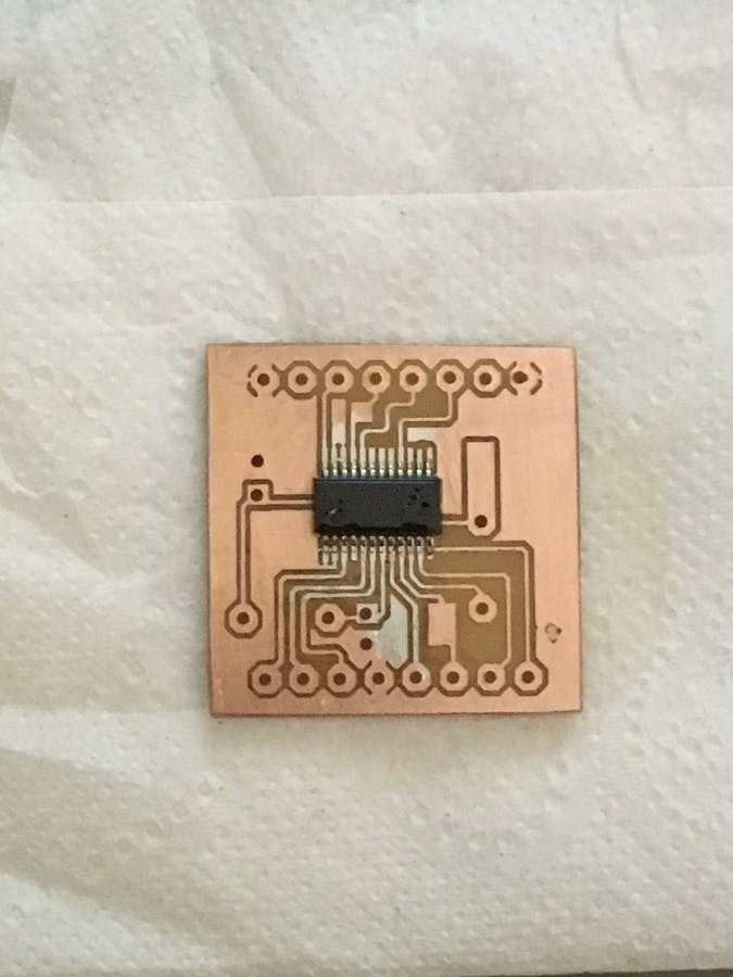
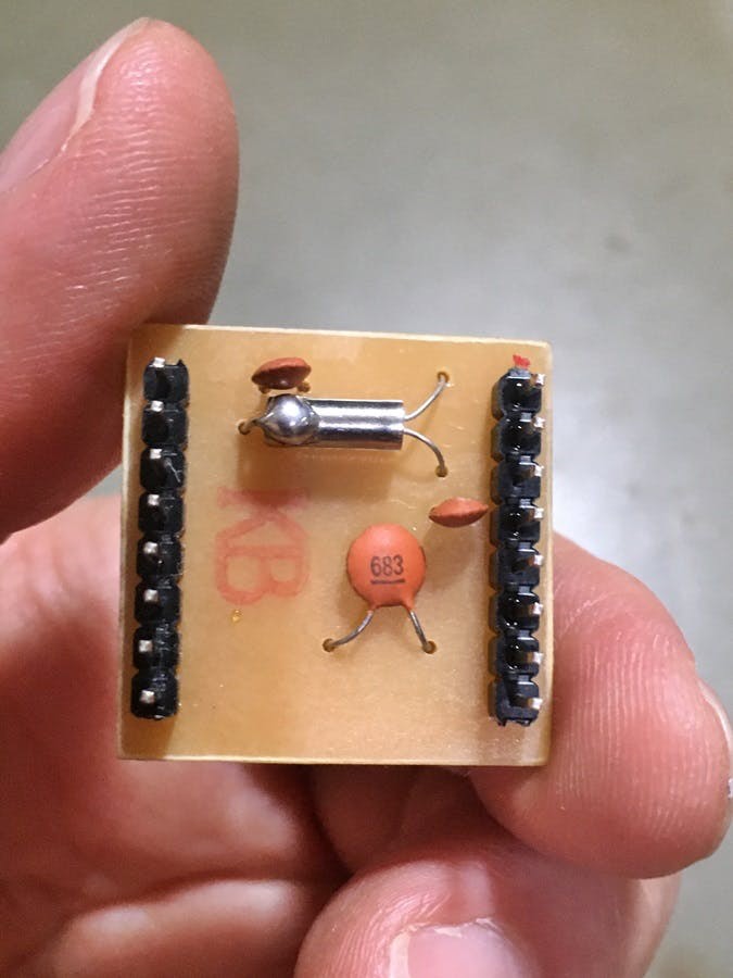
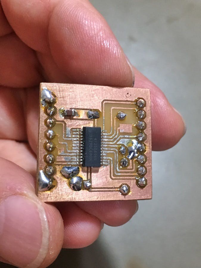
The Si4730-D60, Si4735-D60, Si4734-D60 (SSOP24 package), and Si4732-A10 (SOP16) ICs also work with this project, but they require a breakout board, a 32.768 kHz crystal oscillator, and ceramic capacitors. If you want to build your own Si4730 (SSOP24) breakout board, see the DIY project I made using the thermal (laser print/iron transfer) method. Schematics and PCB layouts are provided in the schematics section.
1 / 9
The DIY LM386 audio amplifier project I assembled at home is shown below, with schematics and PCB layout:
1 / 2
DSP ICRadio Specifications:
This is the block diagram of chip (IC) Si4730(3x):
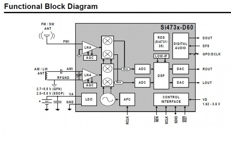
The Si473x-D60 digital CMOS AM/FM radio receiver IC integrates the complete broadcast tuner and receiver function, from antenna input to audio output. Key features include:
- Worldwide FM band support (64–108 MHz)
- Worldwide AM band support (520–1710 kHz)
- SW band support (Si4734/35 and Si4730-D60) (2.3–30 MHz)
- LW band support (Si4734/35 and Si4730-D60) (150–510 kHz)
- Excellent real-world performance
- Automatic frequency control (AFC)
- Automatic gain control (AGC)
- Digital FM stereo decoder
- Advanced Audio Processing
- Seven selectable AM channel filters
- AM/FM/SW/LW digital tuning
Library installation and notes about the sketch:
- Install and use the libraries located in the “install these libraries” folder.
- Choose the correct I²C address for your Si4730/35 (0x11 or 0x63). The PL102BA-S V2 uses address 0x63
- For Si4730/31/34/35-D60 ICs, use 10k pull-up resistors on each I²C line. Pull-ups are not required for the PL102BA-S module.
- Carefully read the instructions in the sketch header.
About the antenna to be used:
- For SW, use an external long wire antenna with a ground connection for best reception. MiniWhip and magnetic loop antennas can also be used.
- For MW/LW, use a standard ferrite stick antenna (12 cm x 1 cm or larger for improved reception).
- For FM, a 70 cm whip or wire antenna is sufficient. For DX reception, use a commercial VHF/FM antenna.
Some tips to improve radio reception:
- Always power the circuit with batteries. I use two 18650 batteries in series (7.8 V) applied to the Arduino VIN pin.
- Avoid switched-mode power supplies or DC-DC step-down converters, as they generate interference around 150 kHz and will disrupt reception. Some power banks also use converters.
- Keep the receiver away from electronic lamps that generate interference. Use LED lamps where possible.
- Avoid class D (PWM) audio amplifiers, as they generate high-frequency noise.
- SW/MW reception depends on propagation. Late afternoon and night are generally best for long-distance reception.
Final considerations on Arduino digital noise:
Every digital circuit with a microcontroller and I²C/SPI buses generates electromagnetic noise that can affect radio reception. To reduce interference:
- Place an insulated metallic plate (steel, aluminium, or copper) under the breadboard and connect it to GND.
- Or assemble the circuit inside a grounded metal enclosure.
- Keep wires as short as possible between the Arduino and TFT.
- Place the DSP radio chip as far as possible from the Arduino and display, ideally in a separate grounded compartment.
---------------------------------------------------------------------------------
New features, bug fixes, performance improvements, and reduced digital noise emission. Download version 2.1, the most up-to-date release. It includes the main sketch, required libraries, and wiring diagrams. click here.
Updated videos showing the receiver in action:
Good luck in assemblies! J. CesarSound.
Schematics, diagrams and documents
Code
Credits
Related products


Leave your feedback...