





Self-driving Rc Car Build

Made by engineering-dads / 3D Printing / Artificial intelligence / Robotics / Vehicles
About the project
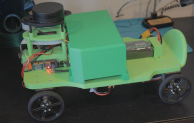
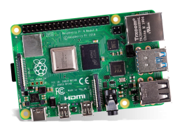
is is a self-driving RC car running entirely on a Raspberry Pi 4. No cloud, no offloading, no external processing. Everything happens on the one board. It has three autonomous modes and I genuinely did not expect all three to work this well by the end of it.
Project info
Difficulty: Difficult
Platforms: Adafruit, Raspberry Pi, OpenCV
Estimated time: 4 weeks
License: GNU General Public License, version 3 or later (GPL3+)
Items used in this project
Hardware components





View all

Story
WHAT WE BUILT
This is a self-driving RC car running entirely on a Raspberry Pi 4. No cloud, no offloading, no external processing. Everything happens on the one board. It has three autonomous modes and I genuinely did not expect all three to work this well by the end of it.
Mode 1 is obstacle avoidance autopilot. The RPLidar A1M8 spins and fires out a laser pulse eight thousand times a second, building a live 360 degree map of whatever is around the car. The software divides that map into zones and if anything enters the forward zone below a threshold distance, the car turns away. Simple in principle, surprisingly fiddly to tune. There was a phase where it just pinged back and forth between two walls forever, which led to the recovery behaviour you see in the code where it reverses and turns before trying forward again.
Mode 2 is dog following. The camera detects the largest object in frame using OpenCV, locks onto it, and steers to keep the bounding box centred. The car speeds up if the target moves further away and slows down if it gets close. This worked brilliantly. It worked so brilliantly that the car followed my dog at speed straight into a chair leg and completely wrote off the original camera. That cost me about a week. New camera, sturdier mount, slightly lower speed cap. We moved on.
Mode 3 is lane detection. Two strips of masking tape on the floor, thirty centimetres apart. The car needs to stay between them. This sounds trivial and it is absolutely not trivial. The key thing I kept getting wrong was trying to tune the steering logic before the vision pipeline was actually working. Once I went back and verified what the camera was actually seeing after processing, and got the colour thresholds and masking region right, everything else clicked into place. This took over thirty rewrites to get to a point where it works consistently enough to demo. For a Raspberry Pi and a consumer camera module, I will take it.
WHAT IS ATTACHED
Three things are attached to this post.
The first is the full wiring diagram. This covers the battery trunk, power distribution, ground hub, motor drivers, encoder signal path through the 74LVC245 level shifter, I2C devices, and the UBEC 5V rail. It also has the recommended wire gauges for each section because getting that wrong is how you get fires or voltage drop problems. If you are building this yourself, read the wiring diagram before you touch anything.
The second is the full parts list. Everything in the build with enough detail to actually source it. There are a couple of notes in there about substitutions I made along the way, including the step down converter that I blew up and had to replace.
The third is the code. It is the full Python project, structured properly with separate files for each mode and each hardware component. I have kept everything clean and documented so it is actually readable. The config file has every tunable parameter in one place so you are not hunting through multiple files to adjust a threshold. The README has setup instructions including the systemd service configuration for auto-starting on boot, and the one-line command you need to run to fix the serial port permissions on the Pi before the LiDAR will work.
A note on the code: the INA219 battery monitor is on I2C address 0x41 rather than the default 0x40. That is because I soldered the A0 bridge on the chip to move it off the default address. If you are using a stock INA219 without that modification you will need to change the address in config.py back to 0x40.
A FEW THINGS I WOULD DO DIFFERENTLY
Design for cable management from the start. I did not. The wiring rat nest you see in the video is what happens when you design the chassis around the electronics without thinking about how the cables actually route. I ended up printing a cover panel to hide it which is a workaround, not a solution.
Put pull-down resistors on your PWM signal lines from the start. Without them, the motors spin randomly during PCA9685 initialisation which is alarming the first time it happens. The software kill commands are not reliable enough. Ten kilohm resistors to ground on each PWM line is the proper fix.
Protect your camera. Mount it recessed. Give it a bump guard. Or just accept that at some point you are going to drive into something at speed and the camera is going to take the hit.
WHAT COMES NEXT
I talked about a few ideas on camera with Sean during the build and there are a couple of directions this project could go next. I will do a proper post about that once the video settles.
Credits
Related products


Leave your feedback...