
World's Fastest 3d Printed Bo Motor Wheel

Made by padmalaya_rawal / 3D Printing / Drones / Robotics
About the project
Faster alternative to regular BO Motors.
Project info
Difficulty: Moderate
Estimated time: 3 hours
License: GNU General Public License, version 3 or later (GPL3+)
Items used in this project
Hardware components

Hand tools and fabrication machines
Story
Overview:
Please watch this animation to know what's inside the project
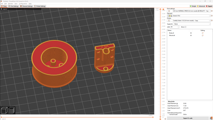
STEP 1: 3D Print the Parts
So, here we just have two parts to be 3D printed which are as follows. So, after watching the animation, you might now be familiar where we are going to use them. If not, don't worry, I have explained each step in detail in upcoming steps. For now, just download, slice and 3D print them. I am using Prusa slicer, but you can use any slicer of your choice. There is no need of support to print them, so print re-orient them if needed. 30-50% infill will be more than enough.
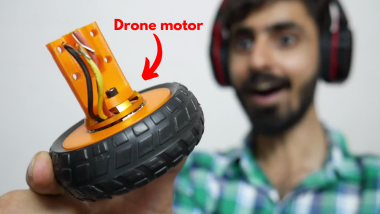
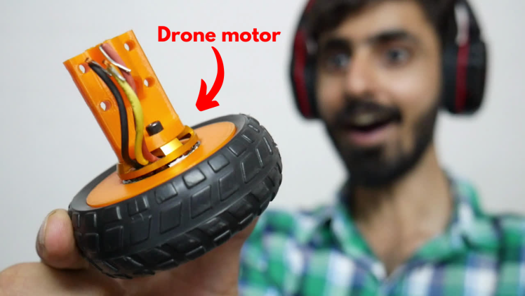
STEP 2: Modification
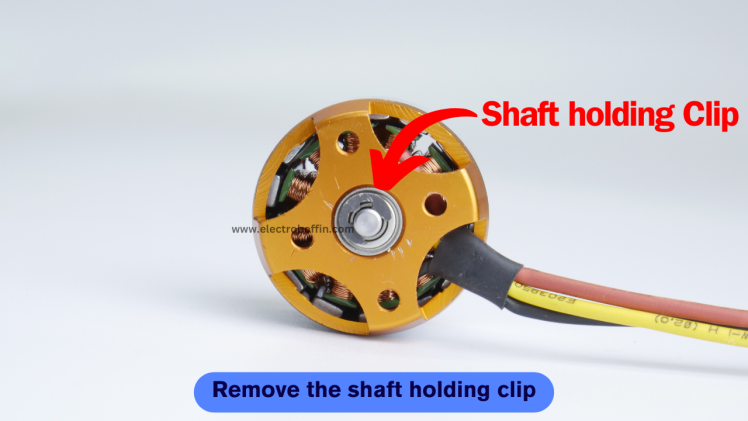
- Remove the shaft holding clip: Firstly, we have to remove the shaft holding clip which is used to keep the prevention the detachment of top part when the propeller is attached on it due to thrust. Take a sharp object is pull it sideways. Without the removal of this clip, you won't be able to separate the upper and lower half of the motor.
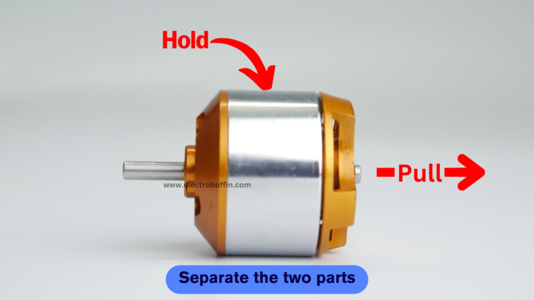
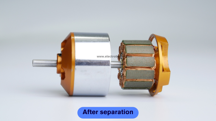
- Separate the Upper and Lower Parts: Now, you can easily pull the upper and lower half of the motor. Be careful while doing this because when you will try to pull the lower part out at the same time the magnets inside the motor will try to pull the lower part inwards as a result of which you may get harmed if your finger will be in between the upper and lower part.
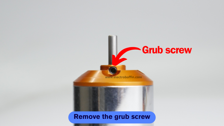
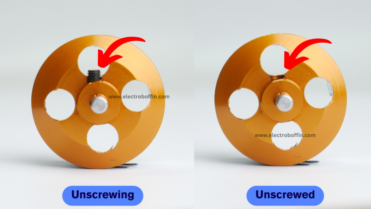
- Remove the Grub Screw: There is a grub screw that hold the shaft in place and prevent any dislocation of the shaft while working. We have to remove it because we have to adjust the height of the shaft.
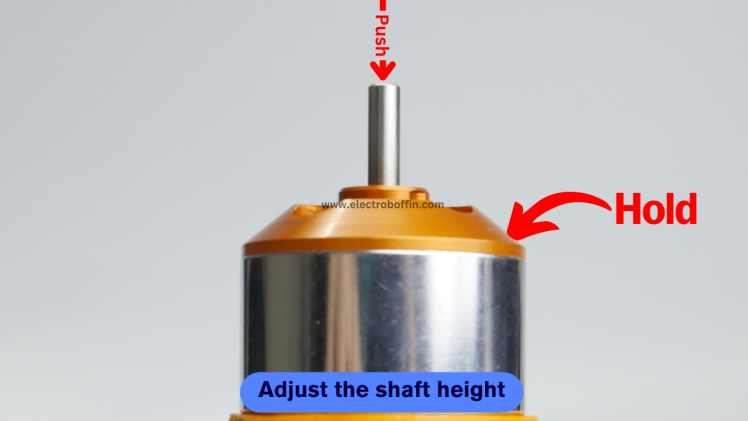
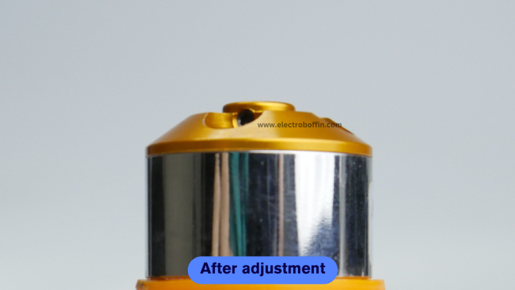
- Adjust the Shaft Height: As, grub screw is now removed, you can place the upper part of the motor on the suitable surface so that the shaft can go down while pressing. You have to apply a lot of pressure here, I have used a hammer to do the same.
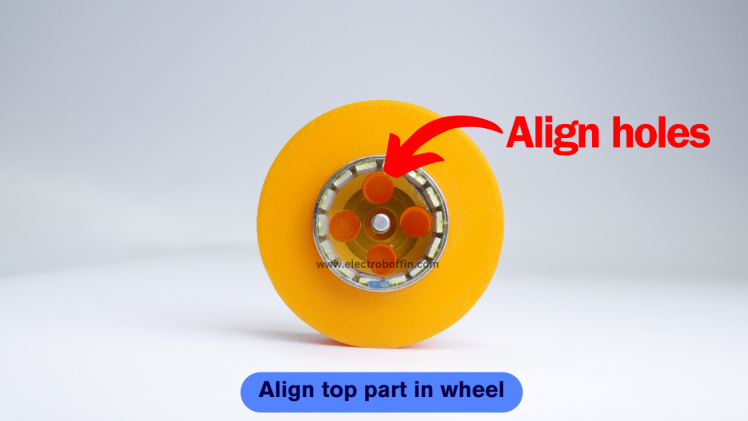
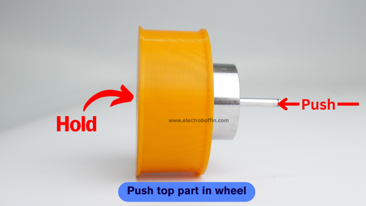
- Align Top Part in Wheel: As the inner section of the motor will rotate at very high speed as a result of which the 3D printed part will not be able to move with it because we are not using any adhesive here. So, to make the 3D printed part move with the motor, I have added 4 support pins that will go inside the holes and help the 3D printed part move with the motor.
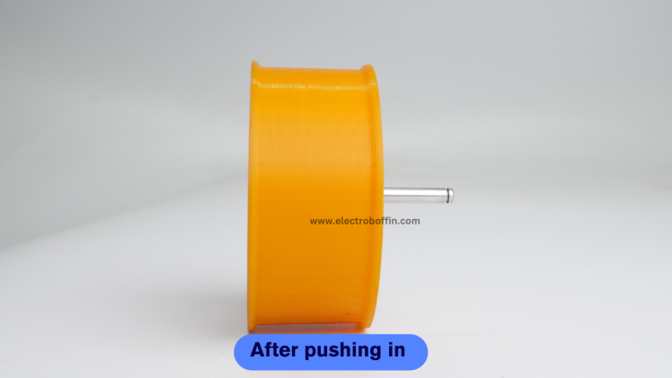
- Push Top Part in Wheel : Once you have aligned the holes with the support pins, press the motor inside the 3D printed part.
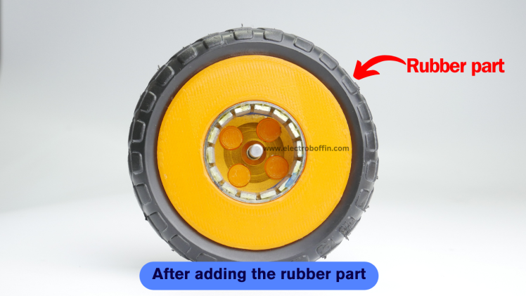
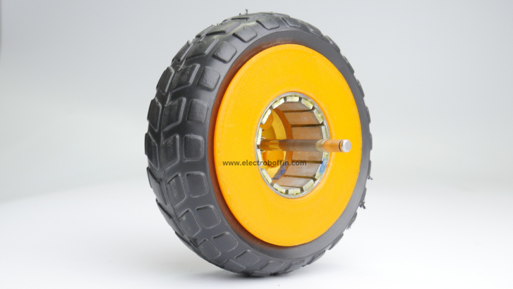
- Add Rubber Part: Now add the rubber part on the 3D printed part. I have removed the rubber part from an inexpensive BO Motor wheel which save my designing and printing time.
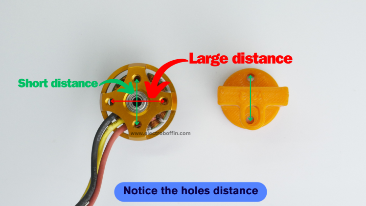
- Notice the Holes Distance for Mount: Notice the distance between the holes which are opposite to each other. One set of holes have shorter distance as compared to the other set. And we will be using this set with shorter distance to connect our 3D printed mount.
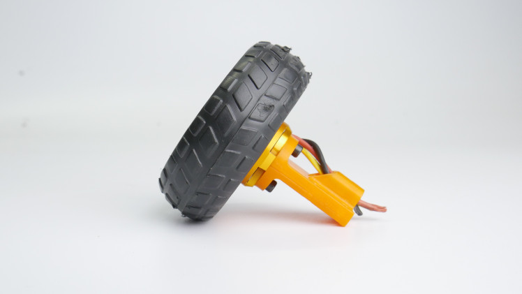
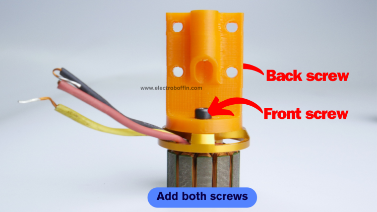
- Add Screw to Join Mount With Bottom Part: Place the 3D printed mount as mentioned above and add the screw that came with the motor
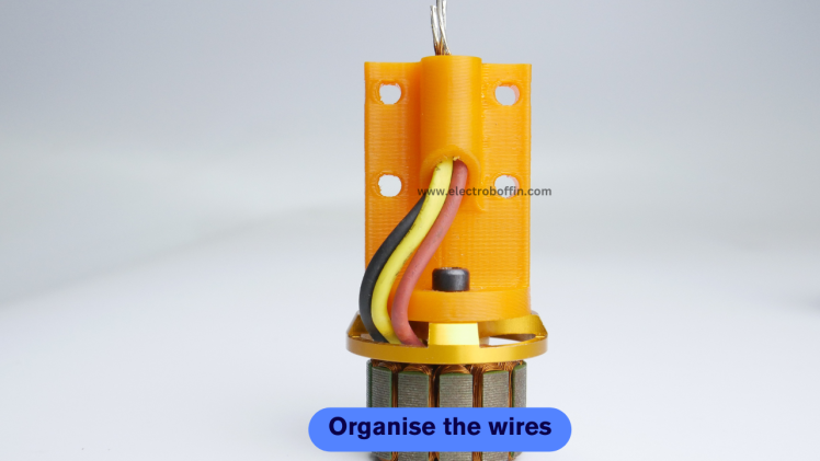
- Organize the Wires: To avoid tangling of wires, pass the wires through hole as shown in image.
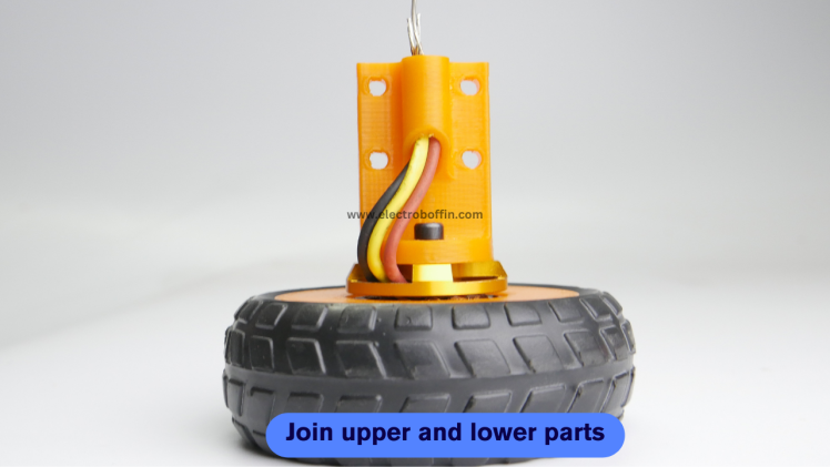
- Join the Upper and Lower Parts: This is the final assembly step, join the upper and lower half and your wheel is now ready to rock on.
I am operating it at 50% of its limit because at full throttle, it goes like crazy, and I have to hold it with two hands which I am unable to do so because I also have to control the speed using ESC Tester.
How I calculated the RPM?
RPM = KV of motor X Battery voltage = 1400KV X 11.1V = 15540.
Working:
For more details:
My website (Ads Free): https://electroboffin.com/worlds-fastest-3d-printed-bo-motor-wheel/
Instructables: https://www.instructables.com/Worlds-Fastest-3D-Printed-BO-Motor-Wheel/
Patreon (For exclusive & latest projects): https://www.patreon.com/electroboffin
All links: https://links.electroboffin.com
--------Thank you so much for reading?------
CAD, enclosures and custom parts
Credits
Related products


Leave your feedback...