Word Clock - Customisable And Easy To Build
About the project
WIN ELECTROMAKER SWAG! Simply submit your code improvements or suggestions for this project in the comments section at the bottom of the page. The top 5 comments will win an Electromaker swag bag. Have your clock tell you the time in full written sentences by lighting up hidden words in a grid of random letters. The face can also be easily swapped once complete to give it almost any style or look you like.
Project info
Difficulty: Easy
Platforms: Arduino
Estimated time: 2 hours
License: GNU General Public License, version 3 or later (GPL3+)
Items used in this project
Hardware components
Story
My partner saw a clock in a shop that told you the time by lighting up words to write a full written sentence from what seemed a jumble of random letters. We liked the clock, but not the price - so we decided to make one of our own design.

I've written instructions below, but you can also watch the video tutorial here:
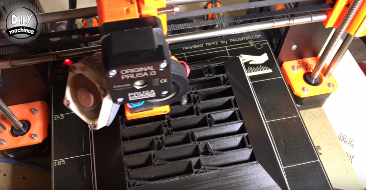
The first thing you need to do is print the main body of the clock. This print is the largest of all the prints and may take some time depending on your chosen layer height.
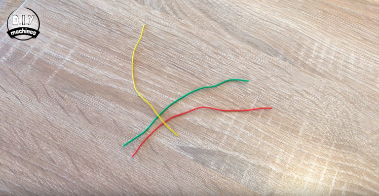
Whilst that is printing you can start assembling some of the electronics. You'll need three wires about 9cm long to start with. Strip a bit of insulation off each end so that we can solder these between our Neomatrix and Arduino Nano.
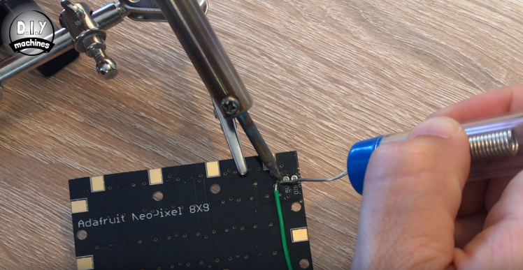
We will solder these three to the Neomatrix. If you look on the reverse of the Neomatrix you will find two groups of three soldering points. One has a point labelled DOUT and the other has one labelled as DIN. We want to solder each on of our three wires to the group of points with the labels, GRND, 5V and DIN (Digital in).
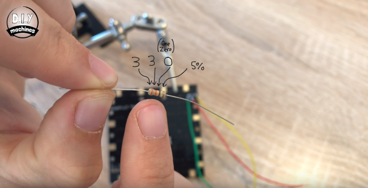
Once you have all three attached we will add a 330 Ohm resistor to the wire we attached to digital in. This the colour markings of a 330 ohm resistor (Orange-Orange-Brown-Gold):
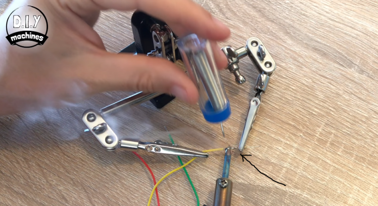
The three wires (one with a resistor on it now) can be attached to our Arduino Nano. Please take a look at the circuit diagram provided in the download section. You'll see you need to solder them as follows:
NeoMatrix | Nano
GRND ---> Ground
5V ---------> 5V
DIN ----Resistor----> D6

Next up we will connect the RTC or Real Time Clock. This is the board which allows our Arduino to remember the time even when it is disconnected from the power. The RTC (we are going to use a DS3231) looks like this:
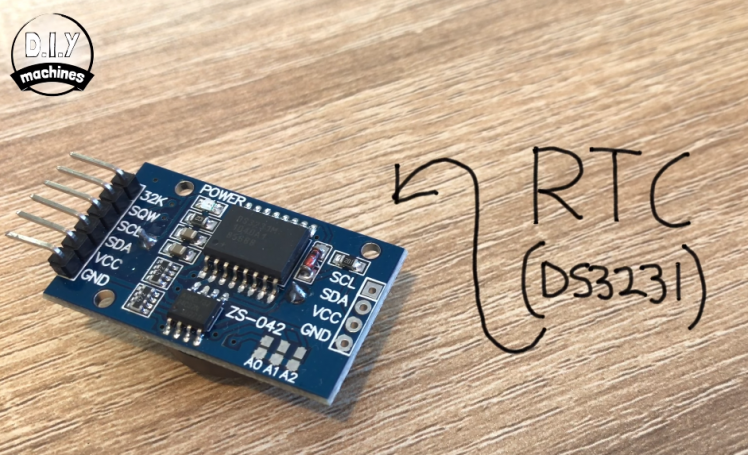
You'll need to prepare four wires this time, and they'll need to be about 6cm in length each. Again strip the ends as we will be soldering these to our components.
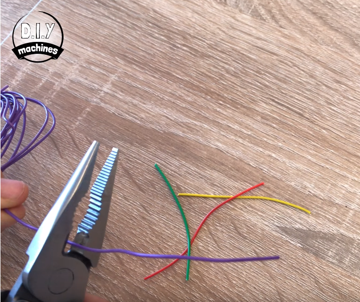
Solder one of each of the wires to the connections labelled SDA, SCL, VCCand GND

This will now be attached to the Arduino Nano. Agaian you can either follow the wiring diagram or for quick reference here is a small table.
RTC | Arduino
VCC ------> 5V (This wire will need to be soldered along with the existing wire from the Neomatrix)
GND ------> Ground
SDA --------> A4
SCL ----------> A5
Next you need to print the main body of the assembly if you have not done so already and we will attach our Neomatrix to it using some hot melt glue.
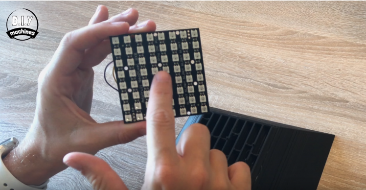
You'll notice the Neomatrix has some mounting holes running through the centre of it. This should align with the six pins on the printed part. We need to ensure that you mount it correctly - the corner of the Neomatrix with our wires attached needs to be located on the corner of the print with the smallest inlet for the light which is this corner:
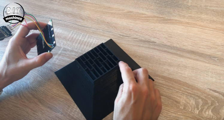
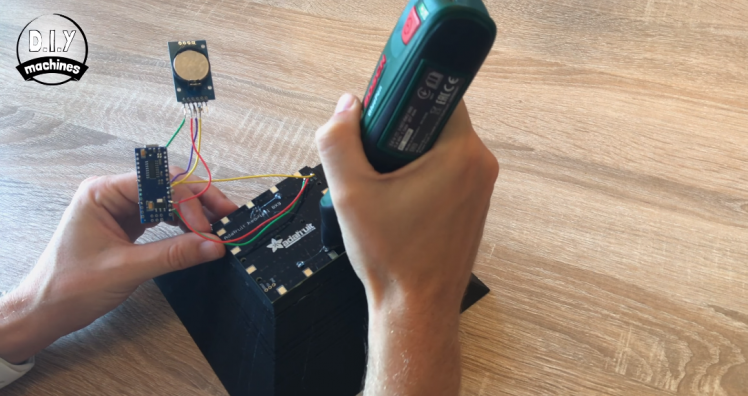
Use some dabs of hot melt glue on the pins that protrude to secure it into position.
Now print the part for the clock stand. You can print this in a different colour if you like. I've done mine in white for some contrast.

We need to glue our other electronic components (the nano and RTC) into place in the back of this enclosure before fixing it to the back of the clock. Start with the Arduino. You need to make sure that once the Arduino Nano is secured you can still connect a USB cable to the it's USB port to power it. There is a hole for this.
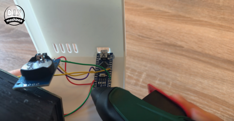
The RTC DS3231 can then also be glued adjacent to this in the same manner.
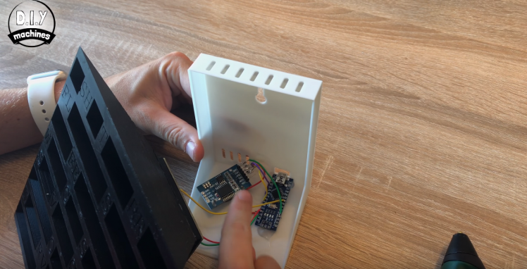
Next up is attaching the stand. You can use the letters that you can already see on the clock front to ensure you glue on the right way up! Position it in place on the back and get the glue gun out again and seal it into place.
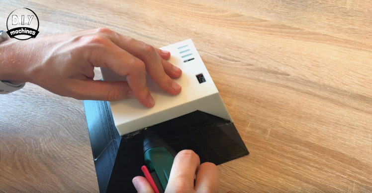
Notice how you can still access the USB port through the hole on the back - if you can't on your you'll want to fix this before securing the stand in place.
To cut the tracing paper to size, lay the Clock on a single sheet (lining it up with one of the corners) and trace around the other two sides. Next cut out this shape, but cut just inside of the line ans we don't want the tracing paper to be bigger then the clock face or it will interfere with changing the clock faces later.
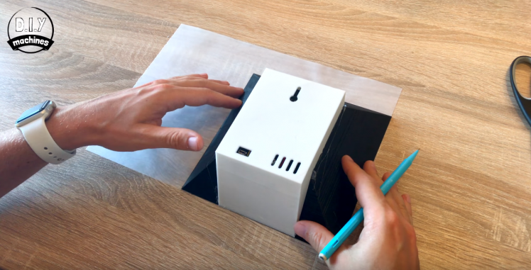
Apply some small dabs of glue to the corners of the clock body and then position the tracing paper onto these. Whilst the glue is setting stretch the sheet our between the corner to try and minimise any wrinkle in the sheet.
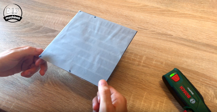
At this point I connected a USB battery pack to the clock to check that everything is still working as it should, luckily mine was just fine.
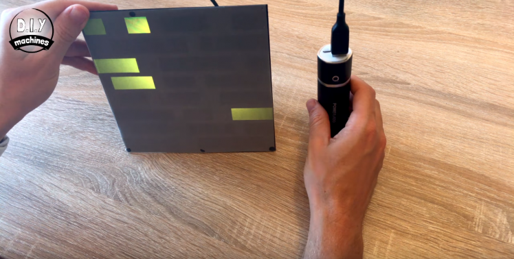
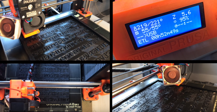
Now we just need to print and slide our clock face over the front of clocks main body.
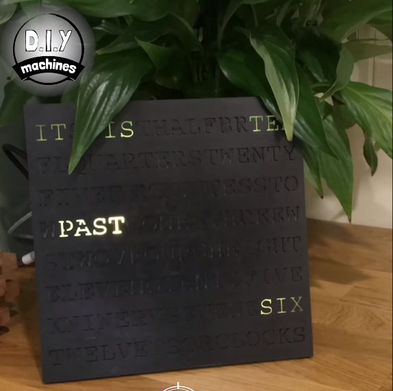
And that's it. You're done. As it's very easy to change the clock face you can print some others in different colours or even why not try making your own. There is a drawing in the downloads section which outline the dimensions you'll need to make it so that it can slide straight onto the front first time.
You'll also find an eye to receive a screw in the back of the stand should you want to wall mount your hard work. :)






Leave your feedback...