
Weather Station Using Dht11 Sensor & M5stack Core Esp32

Made by Ron / Displays / Notifications / Weather / IoT
About the project
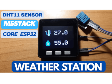
In this tutorial you will learn how to make a simple Weather station using M5Stack Core ESP32 & DHT11 Temperature and Humidity sensor.
Items used in this project
Hardware components

Software apps and online services
Story
In this tutorial you will learn how to make a simple Weather station using M5Stack Core ESP32 & DHT11 Temperature and Humidity sensor.
Watch the video!
Step 1: What You Will Need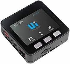
- M5Stack Core ESP32 more info here
- DHT11 Temperature and Humidity sensor
- Jumper wires
- Visuino program: Download Visuino
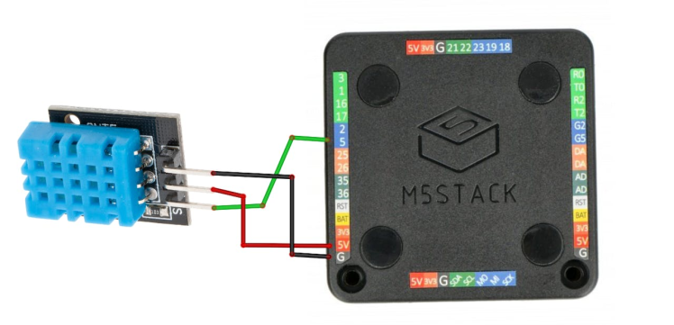
- Connect "DHT11" sensor pin [VCC] to "M5 Stack Core" pin [5V]
- Connect "DHT11" sensor pin [GND] to "M5 Stack Core" pin [G]
- Connect "DHT11" sensor pin [S] to "M5 Stack Core" digital pin [5]
1 / 2
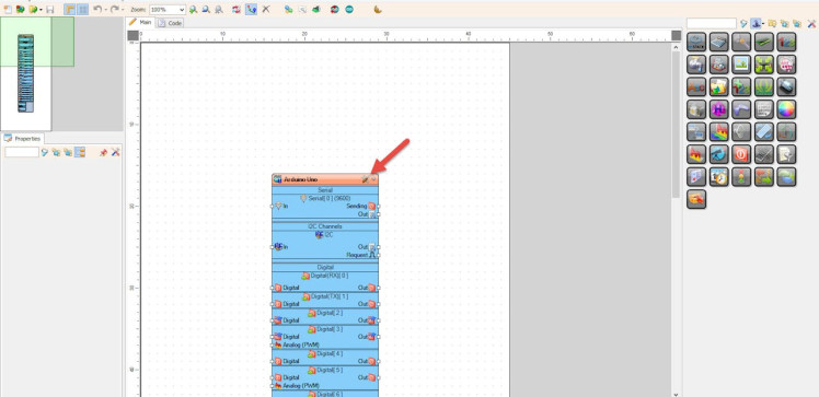
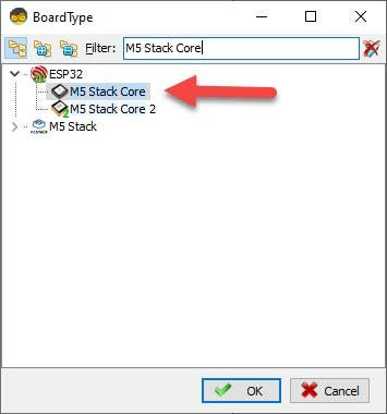
Start Visuino as shown in the first picture Click on the "Tools" button on the Arduino component (Picture 1) in Visuino When the dialog appears, select "M5 Stack Core" as shown on Picture 2
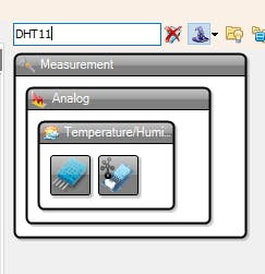
Step 4: In Visuino Add Components1 / 2
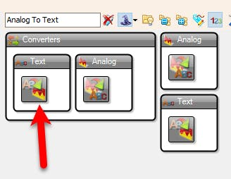
- Add "Analog To Text" component
- Add "DHT11" component
1 / 8
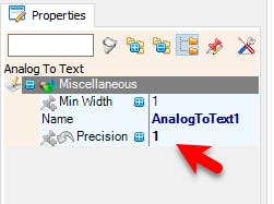
- Select "AnalogToText1" and in the Properties window set "Precision" to 1, this way we will only display one decimal, example 25.6
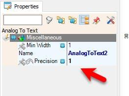
- Select "AnalogToText12 and in the Properties window set "Precision" to 1
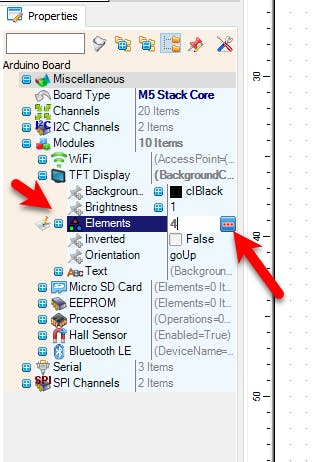
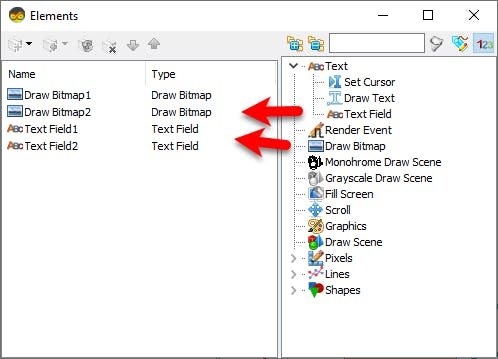
- Select M5 Stack Core and in the editor Modules>TFT Display>Elements, click on [...] button, so that "Elements" window will open.
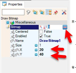
- In the Elements window drag "Draw Bitmap", and in the Properties window set "X" to 20, "Y" to 40 and Select "Bitmap" and click on [...] button, Load the Bitmap for the Temperature, Ideal size is 64X64
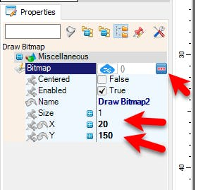
- In the Elements window drag another "Draw Bitmap", and in the Properties window set "X to 20, "Y" to 150 and Select Bitmap" and click on [...] button, Load the Bitmap for the Humidity, Ideal size is 64X64
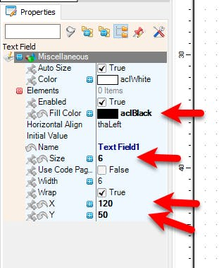
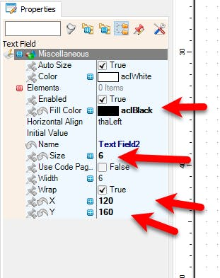
- In the Elements window drag "Text Field" and in the Properties window set "X to 120, "Y" to 50 and "Size" to 6
- In the Elements window drag another "Text Field" and in the Properties window set "X to 120, "Y" to 160 and "Size" to 6
- Close the "Elements" window
1 / 2
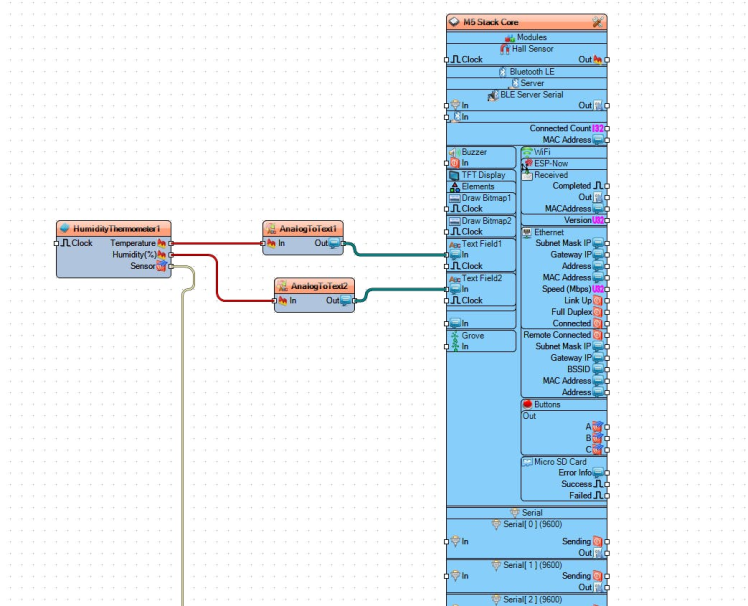
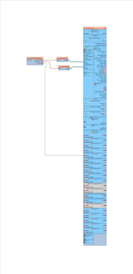
- Connect "HumidityThermometer1" pin [Sensor] to "M5 Stack Core" digital pin [GPIO 5]
- Connect "HumidityThermometer1" pin [Temperature] to "AnalogToText1" pin [In]
- Connect "HumidityThermometer1" pin [Sensor] to "AnalogToText2" pin [In]
- Connect "AnalogToText1" pin [Sensor] to "M5 Stack Core" > "Text Field1" pin [In]
- Connect "AnalogToText2" pin [Sensor] to "M5 Stack Core" > "Text Field2" pin [In]
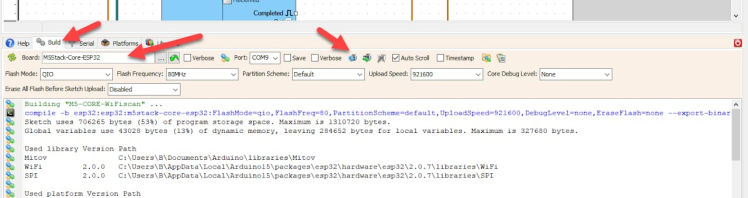
In Visuino, at the bottom click on the "Build" Tab, make sure the correct port is selected, then click on the "Compile/Build and Upload" button.
Step 8: PlayIf you power the M5 Stack Core, the display should start showing the current Temperature and Humidity that it gets from the DHT11 sensor.
Congratulations! You have completed your Internet Time project with Visuino. Also attached is the Visuino project, that I created for this Tutorial. You can download and open it in Visuino: https://www.visuino.eu
Schematics, diagrams and documents
Code
Credits
Related products


Leave your feedback...