
Visuino: Nextion Lcd Based Acceleration To Angle Display

About the project
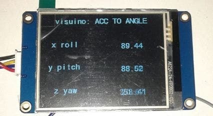
Connect Accelerometer to Arduino, convert the X,Y,Z Values to Roll, Pitch, Yaw, and display it on Nextion display - quick and easy!
Project info
Difficulty: Easy
Platforms: Arduino, Itead, Visuino
Estimated time: 1 hour
License: GNU General Public License, version 3 or later (GPL3+)
Items used in this project
Hardware components

Software apps and online services
Story
1 / 2
I am always a fan of display modules and after coming across Visuino Nextion support I could not resist myself so I decided to use it with my custom designed interface (however after this tutorial everyone can design their own).
Visuino not only simplifies the process but also saves so much time, so your display starts working in minutes.
Some of the images in the tutorial are borrowed from the Mitov Tutorials, and he has helped with some of the final editing of this tutorial.
Components
1 / 4
1 / 6
- Make sure you have a fat32 formatted SD card.
- Make sure you have a plain black wallpaper of 320*240 size. You can make one in MS Paint.
- Optionally you can also add your own background image for the display. In the final version of the project I added image with the Visuino logo on it.
- Make sure you have generated font otherwise Nextion editor will show error in compiling.
- Please be aware that there are some critical bugs in Arduino IDE 1.6.6. Make sure that you install 1.6.7 higher, otherwise this Tutorial will not work!
NOW FOLLOW THESE STEPS:
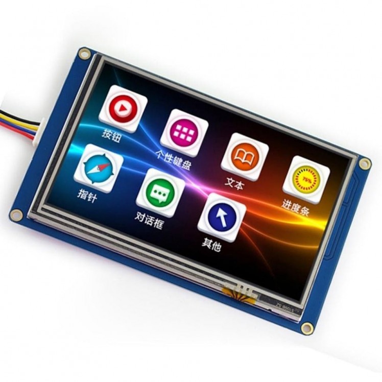
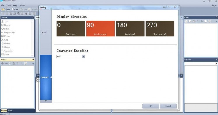
- CLICK new project->name it as Visuino->device tab->choose nx3224t028_011 display->90 horizontal->character encoding ->ASCII
- Display area will have a white 320*240 editable screen.
- Now we have generate fonts: tool->font generator->follow the wizard and select the generated font.
- Now in Nextion editor add the black wallpaper to the picture window (left bottom corner window) by clicking on + button. The black wallpaper will appear in the picture window as picture 0.
- In the display window the white screen will appear. Now click on its attribute table (right hand bottom corner) click on sta->select imagepic->double click->select picture 0 (black wallpaper). Now you will see that white screen becomes black in color. This will be used as the background of the interface.
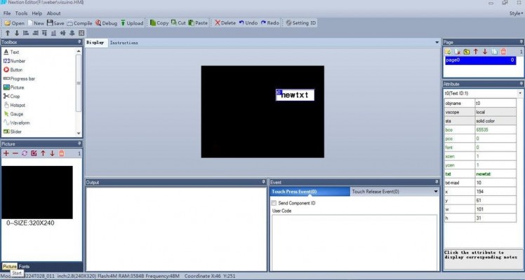
- Now from toolbox window: click on text component->t0 new text will appear on the display. Screen->drag over required area. Now click on its attribute table sta->crop image pic->double click->choose picture 0 pco->choose cyan color txt->x
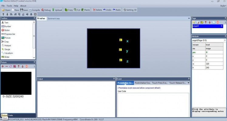
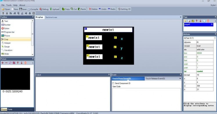
- Similarly repeat the process of adding two more text component t1 , t2. Place them one below the other by dragging them on screen.
- Now you should add 4 more text components to display roll, pitch, and yaw text also by repeating the above procedure.
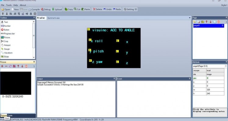
- Click on compile tab (this will generate tft file)
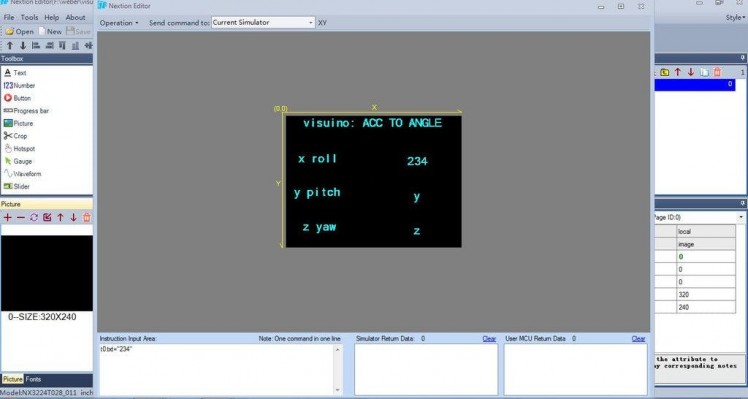
- You can also debug or run this in simulator by clicking on debug tab. A new window will pop up under "instruction input area" window enter-> t0.txt="555". This will cause x->555 on display screen.
- Click on file->open build folder->copy this Visuino tft file into your fat32 formatted SD card.
- Insert this SD card into Nextion LCD and power it on. After successful update. Power it off then remove the SD card and power it on again.
Now you should see your Nextion Editor interface on the LCD.
Alternatively, you can use the Visuino tft file attached here and transfer it directly to the SD card.
Start Visuino, and select the Arduino Board type
1 / 2 • Picture 1

Picture 1

Picture 2
- Start Visuino as shown in the first picture
- Click on the "Tools" button on the Arduino component (Picture 1) in Visuino
- When the dialog appears, select Arduino Nano as shown in Picture 2
1 / 4 • Picture 1

Picture 1

Picture 2

Picture 3

Picture 4
- Type "accelerattion" in the Filter Box of the Component Toolbox, then select the "Acceleration To Angle" component and drop it in the design area (Picture 1)
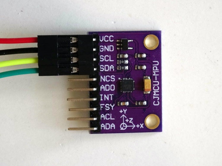
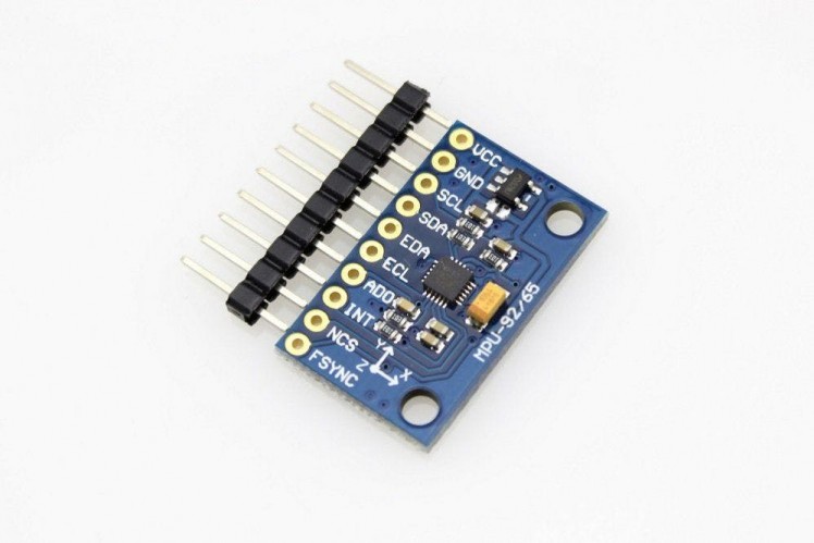
- Type "mpu" in the Filter box of the Component Toolbox then select the "Accelerometer Gyroscope Compass MPU9250 I2C" component , and drop it in the design area (Picture 1)
- Type "next" in the Filter box of the Component Toolbox then select the "Nextion Display" and drag it over design area. (Picture 1)
- Double click the DisplayNextion1 component, and in the Elements Editor, add 3 Text Elements (Picture 2)
- Set the value of the "Element Name" of the second element to "t1" (Picture 3)
- Set the value of the "Element Name" of the third element to "t2" (Picture 3)
- Connect the components as shown on Picture 4
You can use the attached file.
Generate, Compile, and Upload the Arduino Code
1 / 2 • Picture 1

Picture 1

Picture 2
- Please do not connect the display until you upload the code to the Arduino
- Upload to the Arduino through the COM port
- Then connect the display. Otherwise, the code will not upload
In Visuino, Press F9 or click on the button shown on Picture 1 to generate the Arduino code, then go to the Arduino IDE. Click on the Upload button, to compile and upload the code.
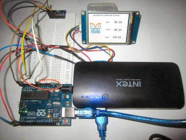
Hardware and jumper connection circuit
1 / 2
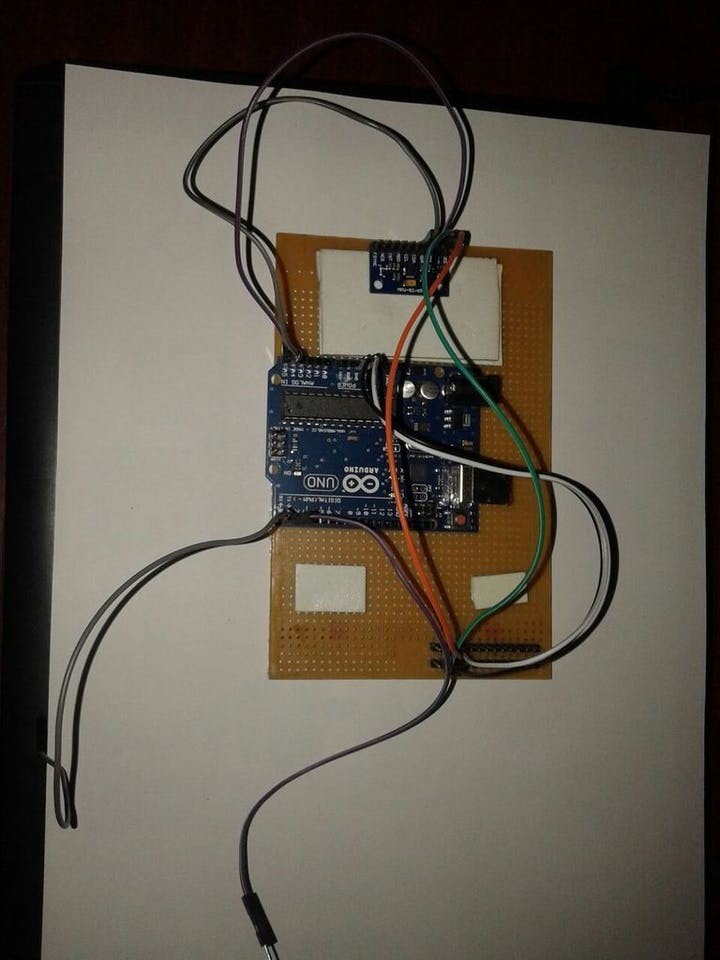
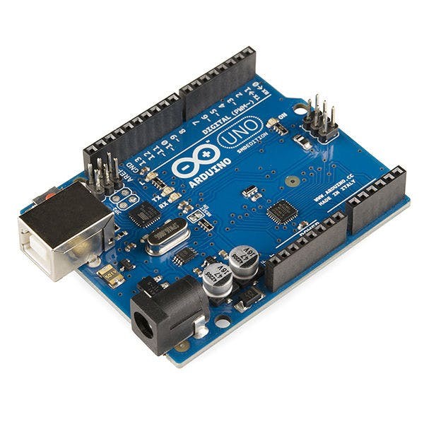
ARDUINO UNO TO MPU9250
- A5 (pin 5) -> SCL
- A4 (pin 4) -> SDA
- VCC -> VCC
- GND -> GND
ARDUINO TO NEXTION LCD
- TX (pin 2) -> RX
- RX (pin 1) -> TX
- VCC (5V) -> VCC
- GND -> GND
1 / 2

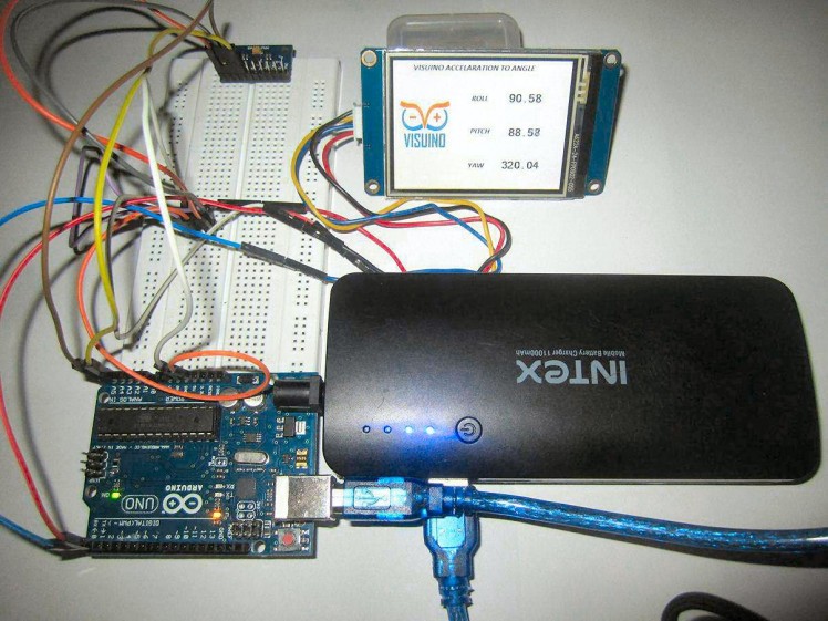
Power up the setup by plugging the USB cable into the Arduino.
The Video is of an earlier version of the project, and does not have the new background with the Visuino logo.
Congrats! You have successfully created the project!
Credits
Related products


Leave your feedback...