

Virtual Fence - Anti Theft Device

Made by akshayan-sinha / Security / IoT
About the project
Use Geo-Fence to secure anything within your SAFE-HOUSE. Edge-computed fence based on GPS and Cellular IoT
Project info
Difficulty: Easy
Estimated time: 2 hours
License: Creative Commons Public Domain Dedication version 1.0 or later (CC0 1+)
Items used in this project


Story
In 2022, over 1 million theft cases, which is a 7% rise compared to 2021, have become a great concern in India. With a population of more than 1.4 billion, you never know whom to trust apart from your own self.
Hence, we are left with only one solution - Track Your Belongings
With the increased availability of devices to access the internet, we all need an automated system, that keeps us updated on our physical product and informs us if it has been moved from its designated location.
But, how do we track them? And how should one get an alert of a theft? We shall see and build a project on that.
What is a Virtual Fence?
A Fence is a physical boundary, which is used to restrict kids and dogs from exiting the border Boundaries provide a layer of security, which also restricts entry from outside. But these boundaries need to be maintained heavily. And once an object has moved out or stolen, then the theft cannot be further located.
This brings us to a solution, which is geofencing a physical device attached to our belonging. This belonging would be a mere part of the IoT - Internet of 'Things'.
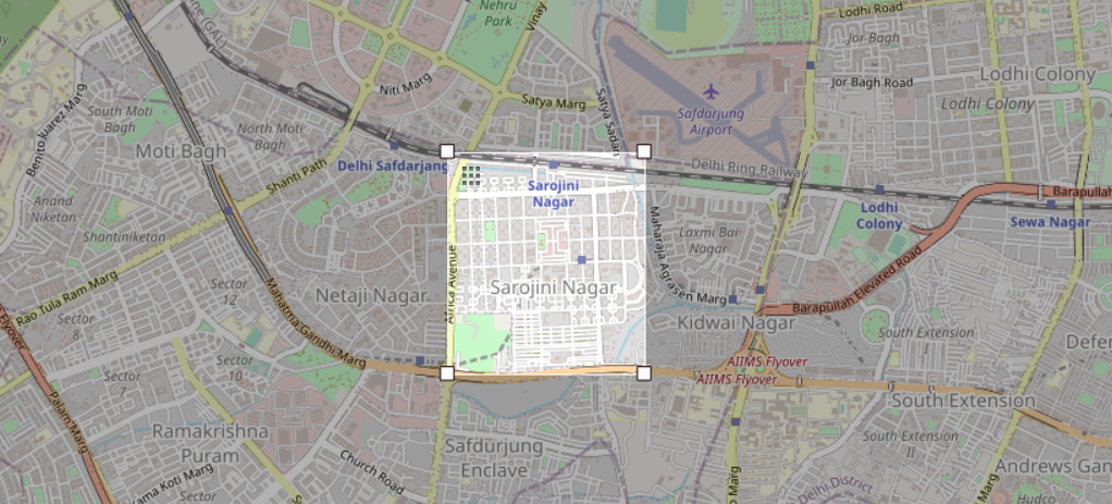
The above pictorial is a sample of Geofence in a public area. Best part? Since it is on a virtual map, having a virtual fence would have no effect on whether you own the area. This area could be your Home, Office, favorite Coffee Shop, or even parlor.
But before we get started -
Get PCBs for Your Projects Manufactured
You must check out PCBWAY for ordering PCBs online for cheap!

You get 10 good-quality PCBs manufactured and shipped to your doorstep for cheap. You will also get a discount on shipping on your first order. Upload your Gerber files onto PCBWAY to get them manufactured with good quality and quick turnaround time. PCBWay now could provide a complete product solution, from design to enclosure production. Check out their online Gerber viewer function. With reward points, you can get free stuff from their gift shop.
Cellular + GPS
To be able to have global connectivity and uninterrupted internet, the ideal network protocol is cellular technology. With a GPS Module attached to it, it is just perfect.
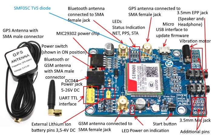
This amazing combination can only be carried by an integrated device. And at the cheapest, we considered SIM808 Module + GPS as the primary module to continue with this project. Let us look more into its features and specifications -
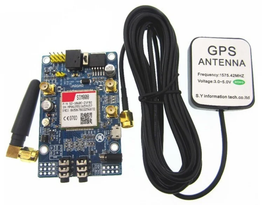
SIM808 GSM :
Supports Quad-band 850/900/1800/1900MHz, compatible with all 2G networks all around the world.
Inner MT3337 GPS receiver, -165dBm precision, control on a same serial port.
Earphone/ microphone outputs on a card or external 32-ohm speaker + supports voice calls with an electret microphone.
Sending and receiving SMS.
Sending and receiving GPRS data (TCP/IP, HTTP vb).
UART communication with automatic baud rate settings.
GPRS multi-slot class 12/10
GPRS mobile station class B
Comply with GSM phase 2/2 +
Class 4 (2 W @ 850 / 900MHz)
Class 1 (1 W @ 1800 / 1900MHz)
Support low power consumption mode: 100mA @ 7V-GSM mode
Support AT command control (3GPP TS 27.007,27.005 and SIMCOM enhanced AT Commands)
Supports GPS satellite navigation technology
Support LED status indicator: Power supply status, network status, and operating modes
Working environment: -40 ℃ ~ 85 ℃
SIM808 GPS :
22 tracking/66 acquisition channel
GPS L1 C/A code
Precision: Tracking: -165dBm,
Cold start: -148dBm
Finding Location Time(typical): Cold start: 32sn, Hot start: 1sn, Warm start: 5sn
Accuracy: ~2.5m
With all these features, it is nearly a handheld portable phone. Yes, you can make a phone call too :P
One grieving concern is, whether going ahead with a smaller size module would fit the portability requirements - Even if a SIM800 module was taken into consideration, for a prolonged secure network that requires more uptime it is a much safer option to go ahead with its successor. Hence, the SIM808 module was chosen for this project. Even though based on availability and price we can always go ahead with the SIM800.
Let us first understand the module and how to get started with a SIM module -
Prologue:
We'll use Arduino UNO to use it as a USB TTL device and send AT commands to SIM808 x module to test the working of the module using PUTTY or Arduino IDE’s Serial Monitor.
Hardware Side -
1. Make following connections > GND of both modules connected to each other.
2. (For PuTTY) TXD of SIM808 connect with TX1 (PIN 1) of Arduino UNO. Similarly RXD ->RX0.
3. (For Arduino) TXD of SIM808 connect with (PIN 10) of Arduino UNO. Similarly RXD ->11.
4. Connect the Arduino UNO to Arduino IDE and upload a default code that does not interface the serial monitor. Eg: Blink LED sketch.
5. Press Normal button for 2 seconds and leave - the Device will start after that. (Different from power sliding switch)
Software side (PuTTy) -
1. Install PuTTY Application software from https://www.putty.org/
2. Change 'Connection Type' to 'Serial'.
3. Enter Serial port on PuTTY. eg: COM8 > With baudrate as '9600'.
4. Click on 'Open' to open the serial terminal
Software side (Arduino IDE) -
Use the below code -
#include <SoftwareSerial.h>
SoftwareSerial mySerial(10, 11);
void setup() {
    Serial.begin(9600);
    mySerial.begin(9600);
}
void loop() {
    Serial.println("AT");
    if (mySerial.available()) {
        Serial.write(mySerial.read());
    }
    if (Serial.available()) {
        mySerial.write(Serial.read());
    }
    delay(500);
}
Testing Commands -
- AT - Check serial communication with module | if no response recheck connections / redo connections / loose connection /module turned off
- AT+CMEE=1 - 1 to disable error &the 2 for verbose errors with error codes
- AT+CPIN? - Check SIM availability with module
# Make Phone Calls
- ATD9989758468; - Phone calls to the number - use Mic and Speaker jack for i/o
- ATH - End phone call
- ATA - Pick up phone call when serial monitor says ‘RING’ repeatedly
- AT+CLCC - Check caller number
# Make Text Messages
- AT+CSMP=17,167,0,0 - Avoid error messages or delivery of empty SMS
- AT+CMGF=1 - Text Mode
- AT+CMGS="+917002834895" - Send message to this number
> Enter your message
> //After pressing 'Enter' move to next line or/and Press Ctrl+Z to send the message - AT+CMGS: 55 - Responses with the packet command after a few seconds to show that message was delivered.
- AT+CMGL = "ALL” - Read all messages
# For GPS Coordinates (GNS because using v2.0 of SIM808)
- AT+CGNSPWR = 1 - Turn on GPS module - use 0 to turn OFF
- AT+CGNSSEQ = "RMC" - Proper sequence of NMEA according to RMC
- AT+CGNSINF - Prints Time and GPS according to module - returns 0 if GPS not set. Returns 1 when outdoors for setting with GPS satellite
Now that we know how to use the device, let us understand the logic on preparing a virtual fence, and how to use the Arduino to perform this logic -
Code Breakdown
1. Communication between Arduino & SIM808
#include <SoftwareSerial.h>

SoftwareSerial mySerial(5, 6);
It sets up a SoftwareSerial instance named mySerial using digital pins 5 (RX) and 6 (TX) on the Arduino, which will be used to communicate with the SIM808 module.
2. Function Prototypes and Global Variables
void(* resetFunc) (void) = 0;
void GPS_data();
void check_GPS();
void sendSMS();

char frame[256];

byte GNSSrunstatus;
byte Fixstatus;
char UTCdatetime[15];

char latitude[10];
float latitude_val;

char longitude[11];
float longitude_val;

long lat_val;
long lon_val;

long lat_high;
long lat_low;

long lon_high;
long lon_low;

int lat_check;
int lon_check;

char altitude[8];
char speedOTG[6];
char course[6];
char fixmode[1];
char HDOP[4];
char PDOP[4];
char VDOP[4];
char satellitesinview[2];
char GNSSsatellitesused[2];
char GLONASSsatellitesused[2];
char cn0max[2];
char HPA[6];
char VPA[6];
Pre-declaration of Functions without function body, to inform the program about the existence of function, before defining, so as to manipulate the arrangement within the program.
Global variables like altitude, speedOTG are to be used within the program, and since the device will run indefinitely, the values are most likely to get reset on setting up new locations as Geo-Fencing.
3. Initialization of Arduino with Cellular Device
void setup() {
  Serial.begin(9600);
  mySerial.begin(9600);

  mySerial.println("ATr");
  updateSerial();
  mySerial.println("AT+CSQ");

  updateSerial();
  mySerial.println("AT+CCID");

  updateSerial();
  mySerial.println("AT+CPIN?");

  updateSerial();
  GPS_data();

  lat_high = lat_val + 900;
  lat_low = lat_val - 900;
  lon_high = lon_val + 900;
  lon_low = lon_val - 900;
}
AT+CSQ - Returns the signal strength of the device.
AT+CCID - Read SIM information, which returns the unique Integrated Circuit Card Identifier (ICCID) of the installed SIM card.
AT+CPIN - Checks if the SIM is locked with a PUK code, or whether it is ready to use.
Calling GPS_data() function to initialize the current location, as the center of the Geo-Fence
Next, set the fence around the center by selecting coordinates values with 300m-500m towards lat and long.
4. Hardware - Software Serial Interconnection
void updateSerial()
{
  delay(500);
  while (Serial.available())
  {
    mySerial.write(Serial.read());
  }
  while(mySerial.available())
  {
    Serial.write(mySerial.read());
  }
}- mySerial.write(Serial.read()) : Forwards from Hardware Serial to Software Serial
- Serial.write(mySerial.read()) : Forwards from Software Serial received to Serial Port
5. GPS Module Initialization
void GPS_data(){
  mySerial.println("AT+CGNSPWR=1");
  updateSerial();
  mySerial.println("AT+CGNSSEQ="RMC"");
  updateSerial();
  mySerial.println("AT+CGNSINF");
  check_GPS();
}- AT+CGNSPWR = 1 : Turns ON the SIMCOM module
- AT+CGNSSEQ=RMC : Configure the GPS module for settings (RMC - Time, date, position, course and speed data)
- AT+CGNSINF : GNSS navigation information parsed from NMEA sentences
Next, let us call check_GPS() function to update the current GPS data.
6. Update GPS Data
void check_GPS(){

  ...
}
This function includes the main section of the whole project, which requests for the current GPS location, and then checks whether it is within the Geo Fence limits. Let us break down the code even further!
7. Initialization of Local Variables for GPS
int8_t counter, answer;
long previous;
counter = 0;
answer = 0;
memset(frame, '�', sizeof(frame));
previous = millis();int8_t counter, answer;: Two variables to keep track of loop iterations and whether the expected response is received.long previous;: Holds the previous time value for timeout calculation.previous = millis();: Initialize current time in milliseconds.char frame[256];: An array to store received characters for constructing the response frame
void *memset(void *str, int c, size_t n)- str − This is a pointer to the block of memory to fill.
- c − This is the value to be set. The value is passed as an int, but the function fills the block of memory using the unsigned char conversion of this value.
- n − This is the number of bytes to be set to the value.
- memset function returns a pointer to the memory area str.
8. Check for Response on UART
do {

    if (mySerial.available() != 0) {
      frame[counter] = mySerial.read();
      counter++;

      if (strstr(frame, "OK") != NULL)
      {
        answer = 1;
      }
    }

}
while ((answer == 0) && ((millis() - previous) < 2000));
This code repeatedly reads characters from the mySerial interface to construct a response frame. It checks if the response contains "OK" to set the answer flag. The loop continues until either "OK" is found or a timeout of 2000 milliseconds is reached. This ensures the program waits for the expected response before proceeding.
9. Parse the String for GPS data
frame[counter - 3] = '�';
strtok(frame, ": ");
GNSSrunstatus = atoi(strtok(NULL, ","));
Fixstatus = atoi(strtok(NULL, ","));
strcpy(UTCdatetime, strtok(NULL, "."));
strtok(NULL,",");
strcpy(latitude, strtok(NULL, ","));
strcpy(longitude, strtok(NULL, ","));
strcpy(altitude, strtok(NULL, ","))frame[counter - 3] = '�';: Terminate the response frame at a specific index.
strtok(frame, ": ");: Tokenize the frame using colons and spaces as delimiters.
GNSSrunstatus = atoi(strtok(NULL, ","));: Get GNSS run status as an integer.
Fixstatus = atoi(strtok(NULL, ","));: Get fix status as an integer.
strcpy(UTCdatetime, strtok(NULL, "."));: Copy UTC date and time.
strtok(NULL, ",");: Skip irrelevant tokens.
strcpy(latitude, strtok(NULL, ","));: Copy latitude.
strcpy(longitude, strtok(NULL, ","));: Copy longitude.
strcpy(altitude, strtok(NULL, ","));: Copy MSL altitude.
This code takes the string data in the frame and then copies it to the variables like GNSSrunstatus, Fixstatus, UTCdatetime, lat, long & altitude.
byte GNSSrunstatus, Fixstatus;: Byte variables to store GNSS run status and fix status.char UTCdatetime[15];: A character array to store UTC date and time.char latitude[10], longitude[11], altitude[8];: Character arrays to store latitude, longitude, and altitude data.
10. Print & Store the Data in the MESSAGE String
if (Fixstatus != 0){

      Serial.println("GPS Data received");

      Serial.print("Runstatus: ");
      Serial.println(GNSSrunstatus);
      Serial.print("Fixstatus: ");
      Serial.println(Fixstatus);
      Serial.print("UTCdatetime: ");
      Serial.println(UTCdatetime);
      Serial.print("latitude: ");
      Serial.println(latitude);
      Serial.print("longitude: ");
      Serial.println(longitude);
      Serial.print("altitude: ");
      Serial.println(altitude);

      latitude_val = atof(latitude);
      lat_val = latitude_val*1000000;
      Serial.println(lat_val);

      longitude_val = atof(longitude);
      lon_val = longitude_val*1000000;
      Serial.println(lat_high);
.
.
.
If Fixstatus does not return '0', it means we have the complete GPS data. And so it can be further used according to our project.
11. Setting the SafeHouse and Alert SMS
if (lat_high == 0){
        sprintf(MESSAGE, "Latitude : %snLongitude : %snAltitude : %s kmnnInitial Position of the Modulennhttp://maps.google.com/maps?q=%s,%sn", latitude, longitude, altitude, latitude, longitude);
        sendSMS();

      }
      else{

        lat_check = inRange(lat_val, lat_high, lat_low);
        lon_check = inRange(lon_val, lon_high, lon_low);
        Serial.print(lat_check);
        Serial.println(lon_check);
        if (!(lat_check)){

          sprintf(MESSAGE, "Latitude : %snLongitude : %snAltitude : %s kmnnALERT!! Module is outside the GeoFencennhttp://maps.google.com/maps?q=%s,%sn", latitude, longitude, altitude, latitude, longitude);
          sendSMS();
    }

}

}
     else if ((Fixstatus == 0) && (lat_high == 0)){
      Serial.println("Resetting Arduino to check GPS data");
      delay(5000);
      resetFunc();
    }
}
If lat_high=0, or a value exists in it, using sprintf() function, we are storing it in the global variable MESSAGE.
This MESSAGE is different for the initial positioning (SafeHouse), & Alerting in case the data is received.
In case, the Fixstatus is again 0 during execution, reset the Arduino to start fresh the connection
12. Send GPS data to Another SIM number
void sendSMS()
{
  Serial.println("Start to send message ...");

  Serial.println(MESSAGE);
  Serial.println(phone);

  mySerial.println("AT+CSMP=17,167,0,0");
  updateSerial();
  mySerial.println("AT+CMGF=1");
  updateSerial();
  String sim_sms = "AT+CMGS="" + phone + ""r";
  mySerial.println(sim_sms);
  updateSerial();
  mySerial.print(MESSAGE);
  delay(500);
  mySerial.print((char)26);
  Serial.println("Check SMS");
}AT+CSMP=17,167,0,0;: This line sends the AT command "AT+CSMP=17,167,0,0" to the SIM808 module. It's used for setting SMS parameters.
AT+CMGF=1;: This line sends the AT command "AT+CMGF=1" to the SIM808 module. It sets the SMS mode to text mode.
String sim_sms = "AT+CMGS="" + phone + ""r";: This line creates a string sim_sms that represents the AT command "AT+CMGS=" followed by the recipient's phone number enclosed in double quotes and terminated with a carriage return.
sim_sms: This line sends the sim_sms command to the SIM808 module. It initiates sending an SMS to the specified phone number.
That's it! Now that we have shared the GPS data using SMS to the specified number, it is in fact a great method to safeguard your belongings!
Working
Let us make the connections between Arduino - SIM808 - GPS Module
Initial Position - After we flash the code to the Arduino, the code sends the initial location of the GPS while creating a Geo-Fence around the center of the location.
SMS Message
Latitude : 23.009152
Longitude : 50.252952
Altitude : 86.200 km
Initial Position of the Module

http://maps.google.com/maps?q=23.009152,50.252952
The device keeps checking its location on a loop, indefinitely Till the time the device is within half a kilometer (500m) of the above location, the device is considered within the safe house.
Geo-Fence Breach - The moment, the device moves out of the GeoFence, the device detects it as an alert and sends an SMS immediately.
SMS Message
Latitude : 24.008693
Longitude : 51.253190
Altitude : 85.000 km
ALERT!! Module is outside the GeoFence

http://maps.google.com/maps?q=24.008693,51.253190
Congratulations! You will be now able to build your own device to GeoFence. We hope that this tutorial has provided you with the information you need to build and learn throughout.
If you have any questions or need further assistance, please let me know in the comments!
Code
Credits
Related products


Leave your feedback...