
Using Passive Photoresistor Sensor With Visuino

Made by Ron / Displays / Environmental Sensing / Sensors
About the project
Learn the hidden tricks when using Photoresistor Sensor with Arduino!
Project info
Difficulty: Easy
Estimated time: 1 hour
License: GNU General Public License, version 3 or later (GPL3+)
Items used in this project

Story
Photoresistors are among the most popular lighting level sensors for Arduino. They are easy to use, and yet, there are some unexpected surprises, especially when we try to use ready modules designed by somebody else.
In this Tutorial I will show you how to connect a ready Photoresistor module to Arduino, how to compensate the signal for the way the module is designed, and how to control a digital signal ON and OFF based on the level of the lighting.
Step 1: Components
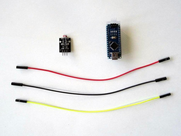
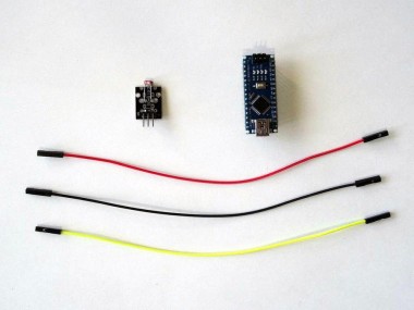
- One Arduino compatible board (I use Arduino Nano, because I have one, but any other will be just fine)
- One Photoresistor Sensor module I got from this cheap 37 sensors set
- 3 Female-Female jumper wires
1 / 3 • Picture 1

Picture 1

Picture 2

Picture 3
- Connect Ground(Black wire), Power(Red wire), and Signal(Yellow wire) to the Photoresistor Module (Picture 1)
- Connect the other end of the Ground wire(Black wire) to the Ground pin of the Arduino board(Picture 2)
- Connect the other end of the Power wire(Red wire) to the 5V power pin of the Arduino board(Picture 2)
- Connect the other end of the Signal wire(Yellow wire) to the Analog pin 0 of the Arduino board(Picture 2)
- Picture 3 shows where are the Ground, 5V Power, and Analog 0 pins of the Arduino Nano
1 / 2 • Picture 1

Picture 1

Picture 2
To start programming the Arduino, you will need to have the Arduino IDE installed from here: http://www.arduino.cc/.
Please be aware that there are some critical bugs in Arduino IDE 1.6.6.
Make sure that you install 1.6.7 or higher, otherwise this Tutorial will not work!
- The Visuino: https://www.visuino.com also needs to be installed.
- Start Visuino as shown in the first picture
- Click on the "Tools" button on the Arduino component (Picture 1) in Visuino
- When the dialog appears, select Arduino Nano as shown in Picture 2
1 / 2 • Picture 1

Picture 1

Picture 2
In Visuino connect the "Out" pin of the Digital[ 14 ]/Analog[ 0 ] channel of the Arduino component (Picture 1) to the "In" input pin of the Serial[ 0 ] channel of the Arduino component (Picture 2).
Step 5: Generate, Compile, and Upload the Arduino code
1 / 2 • Picture 1

Picture 1

Picture 2
- In Visuino, Press F9 or click on the button shown on Picture 1 to generate the Arduino code, and open the Arduino IDE
- In the Arduino IDE, click on the Upload button, to compile and upload the code (Picture 2)
1 / 4 • Picture 1

Picture 1

Picture 2

Picture 3

Picture 4
Picture 1 shows the running project.
Picture 2 shows the complete Visuino diagram.
In Visuino, click on the Scope tab, select serial port, and click on the Connect button (Picture 3)
You should see the data from the sensor plotted on the scope (Picture 4)
If you cover the Photoresistor, you will notice that the value is increasing, and if you point it to light, it is decreasing. The reason is that the Photoresistor in this module has been connected to ground as you will see in the next step.
Step 7: Option 1: Correct the signal by switch the power and ground
1 / 4 • Picture 1

Picture 1

Picture 2

Picture 3

Picture 4
Picture 1 shows how the photoresistor on this module is connected.
Since this is a passive module - there are not any other elements beside the photoresistor, and one other resistor, you can switch the power and ground (Picture 2) and the the connection will become as shown on Picture 3
Picture 4 shows the newly connected project.
If you connect to it with Visuino as shown in the previous step, you will see that this time the value will increase if the light in the photo resistor increases.
Step 8: Option 2: Correct the signal in Visuino
1 / 6 • Picture 1

Picture 1

Picture 2

Picture 3

Picture 4

Picture 5

Picture 6
If you don't want to switch the Power and Ground, you can correct the signal in Visuino by using a Subtract From Value component and subtract from 1.0 :
- Type "sub" in the Filter box of the Component Toolbox then select the "Subtract From Value" component (Picture 1), and drop it in the design area
- Disconnect the old connection between Analog[ 0 ] and and Serial[ 0 ] (Picture 2)
- Connect the "Out" pin of the "Digital[ 14 ]/Analog[ 0 ]" channel of the Arduino component to the "In" pin of the SubtractFromValue1 component (Picture 3)
- Connect the "Out" pin of the SubtractFromValue1 component (Picture 4) to the "In" input pin of the Serial[ 0 ] channel of the Arduino component (Picture 5)
- In the Object Inspector, set the value of the "Value" property of the SubtractFromValue1 component to 1 (Picture 6)
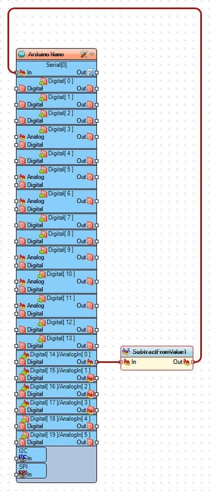
On the picture you can see the completed Visuino diagram.
Generate code, compile and upload as you did in Step 5.
If you connect to Arduino with Visuino as shown in Step 6, you will see that the value will increase if the light in the photo resistor increases.
Step 10: In Visuino: Add a Compare component to control the LED on Digital pin 13
1 / 5 • Picture 1

Picture 1

Picture 2

Picture 3

Picture 4

Picture 5
- Type "com" in the Filter box of the Component Toolbox then select the "Compare Analog Value" component (Picture 1), and drop it in the design area
- In the Object Inspector, set the value of the "Value" property of the CompareAnalogValue1 component to a value between 0.4 to 0.7 (depending on your lighting) (Picture 2)
- In the Object Inspector, set the value of the "CompareType" property of the CompareAnalogValue1 component to ctSmaller (Picture 3)
- Connect the "Out" pin of the SubtractFromValue1 to the "In" pin of the CompareAnalogValue1 (Picture 4)
- Connect the "Out" pin of the CompareAnalogValue1 to the "Digital" input pin of the Digital[ 13 ] channel of the Arduino component(Picture 5)
1 / 3 • Picture 1

Picture 1

Picture 2

Picture 3
Generate code, compile and upload as you did in Step 5.
If you run the project in Arduino, and if there is enough light, the LED on pin 13 will be OFF as shown on Picture 1.
If you cover the Photoresistor, the LED on pin 13 will turn ON as shown on Picture 2.
Congratulations! You have mastered using Photoresistor module with Arduino, and Visuino.
On Picture 3 you can see the complete Visuino diagram.Also attached are the Visuino projects, that I created for this Tutorial. You can download and open them in Visuino: https://www.visuino.com
Credits
Related products


Leave your feedback...